Fuel Injector For High Flame Speed Fuel Combustion

a fuel injector and high flame speed technology, which is applied in the ignition of turbine/propulsion engines, engine starters, lighting and heating apparatus, etc., can solve the problems of low emission, stability, and low emission of hydrogen-content fuels

Active Publication Date: 2016-02-04
CAPSTONE TURBINE
View PDF12 Cites 7 Cited by
  • Summary
  • Abstract
  • Description
  • Claims
  • Application Information

AI Technical Summary

Benefits of technology

[0027]In any of the above embodiments the annular near-wall layer air stream may be maintained sufficiently free of fuel so as to prevent near-wall layer flashback.
[0028]

Problems solved by technology

Combustion of high-hydrogen-content fuels with low emissions poses some special challenges regarding the fuel injection and overall combustion system.
A high degree of pre-mixing of the fuel and air prior to combustion can

Method used


Image

  • Fuel Injector For High Flame Speed Fuel Combustion
  • Fuel Injector For High Flame Speed Fuel Combustion
  • Fuel Injector For High Flame Speed Fuel Combustion

Examples


Embodiment Construction

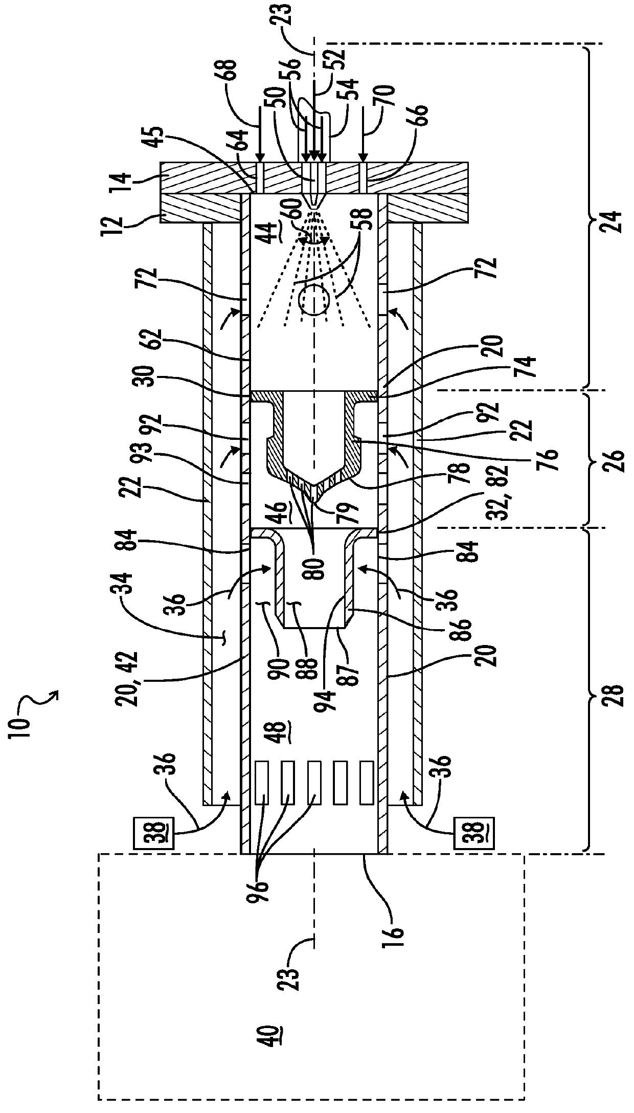
[0041]Referring now to FIG. 1 a fuel injector is shown and generally designated by the numeral 10. The fuel injector 10 is shown somewhat schematically in FIG. 1. Although the general geometry of the injector 10 may vary, in one embodiment the injector 10 is a modularized tubular design with mounting flanges 12 and 14 on one end, and outlet 16 on the other end. In between is the injector body which includes inner and outer concentric tubes 20 and 22. In the embodiment illustrated the fuel injector apparatus 10 has a central longitudinal axis 23.

[0042]As is further explained below with regard to the embodiment of FIG. 6, the outer tube 22 may be an angled injector mounting tube 158 extending through the annular recuperator 123 of a turbogenerator, and the flange 12 may be a mounting boss 156 located on an outer recuperator wall 157. The inner tube 20 in turn may be a fuel injector tube 161 and the flange 14 may be an angled fuel injector flange 155 complementary to the mounting boss ...


PUM


Abstract

A multiple fuel capable, pre-mixed, low emission injector is provided which is particularly suited for burning high flame speed fuels. The fuel injector includes an injector body having a preliminary pre-mixing chamber, an intermediate pre-mixing chamber and a final pre-mixing chamber. A fuel distributor separates the preliminary pre-mixing chamber from the intermediate pre-mixing chamber. A guide vane separates the intermediate pre-mixing chamber from the final pre-mixing chamber.

Description

BACKGROUND OF THE INVENTION[0001]1. Field of the Invention[0002]The present invention relates generally to multistaged prevaporizing pre-mixing fuel injectors, and more particularly, to a fuel injector especially suitable for combustion of high flame speed fuels.[0003]2. Description of the Prior Art[0004]Fossil fuels have been widely used in power generation and other combustion applications. Alternatives to fossil fuels for production of power include use of renewable fuels. For example, one class of fuels is the syngas produced through gasification of feedstocks which results in fuel streams rich in hydrogen. Combustion of high-hydrogen-content fuels with low emissions poses some special challenges regarding the fuel injection and overall combustion system. To achieve low NOx emissions in the modern advanced combustion systems, the popular technique is burning the fuel in a lean pre-mixed manner, both for liquid and gaseous fuels. A high degree of pre-mixing of the fuel and air pr...

Claims


Application Information

Patent Timeline
IPC IPC(8): F23R3/28
CPCF23R3/286F23D11/40F23R3/32
Inventor CHEN, JUNHUAMITCHELL, MARKNOURSE, JOHNMCKEIRNAN, JR., ROBERT D.
Owner CAPSTONE TURBINE
Why Eureka
Try Eureka