Resonator structure for a cavity filter arrangement

a cavity filter and resonator technology, applied in the direction of resonators, basic electric elements, waveguide type devices, etc., can solve the problems of small efficiency signal fade, large adjustment requirements, coordination, etc., and achieve the effect of reducing production costs, simple structure, and reducing failures of components and subsystems

Active Publication Date: 2016-02-04
INTEL CORP
View PDF3 Cites 0 Cited by
  • Summary
  • Abstract
  • Description
  • Claims
  • Application Information

AI Technical Summary

Benefits of technology

[0023]The advantage of the present invention is that it achieves an arrangement in which the resonator is obtained in the same number of emission bands. The invention has the advantage that it can be reduced by having the resonators use a device with significantly compared to the known technique's corresponding characteristics reached at the device. In addition, the present invention has the advantage that its structure is simple and thus the production cost is reduced and the failure of components and subsystems decreases. Further, the invention enables the reproducible setting of the same settings produce the same results. The invention also has the advantage that, since the resonance frequency of the set is held in place and does not change with time, because the time varying components can be reduced, When the pieces have been set, the active control is not needed.
is that it achieves an arrangement in which the resonator is obtained in the same number of emission bands. The invention has the advantage that it can be reduced by having the resonators use a device with significantly compared to the known technique's corresponding characteristics reached at the device. In addition, the present invention has the advantage that its structure is simple and thus the production cost is reduced and the failure of components and subsystems decreases. Further, the invention enables the reproducible setting of the same settings produce the same results. The invention also has the advantage that, since the resonance frequency of the set is held in place and does not change with time, because the time varying components can be reduced, When the pieces have been set, the active control is not needed.

Problems solved by technology

Cavity resonators commonly used for making the filters in telecommunications networks, in particular, when the transmitted signal power is relatively high This is because these losses are due to the small size of resonator filters, which means only a small efficiency signal fade.
Such coordination, however, requires a lot of adjustment in order to achieve the desired frequency bands.
Resonance transfer of such a filter is, however, very difficult, because it is taken into account also the links be the resonators.
Structure requires mechanics, so it becomes more expensive than conventional resonators of moving parts because it is more prone to defects.

Method used


Image

  • Resonator structure for a cavity filter arrangement
  • Resonator structure for a cavity filter arrangement
  • Resonator structure for a cavity filter arrangement

Examples


Embodiment Construction

[0029]In the following description, the embodiments are exemplary only and the person skilled in the basic idea of the invention can understand it in some other way than described in the specification. Although the description may refer to one embodiment of the embodiments, or in several places, it does not mean that the target is only in regard to a single reference to the described embodiment or feature of the described which would be useful only in conjunction with the illustrated embodiment. Two or more individual features of embodiments can be combined and thus provide novel embodiments of the invention.

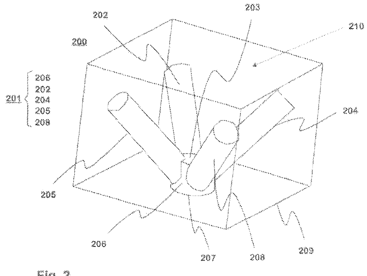
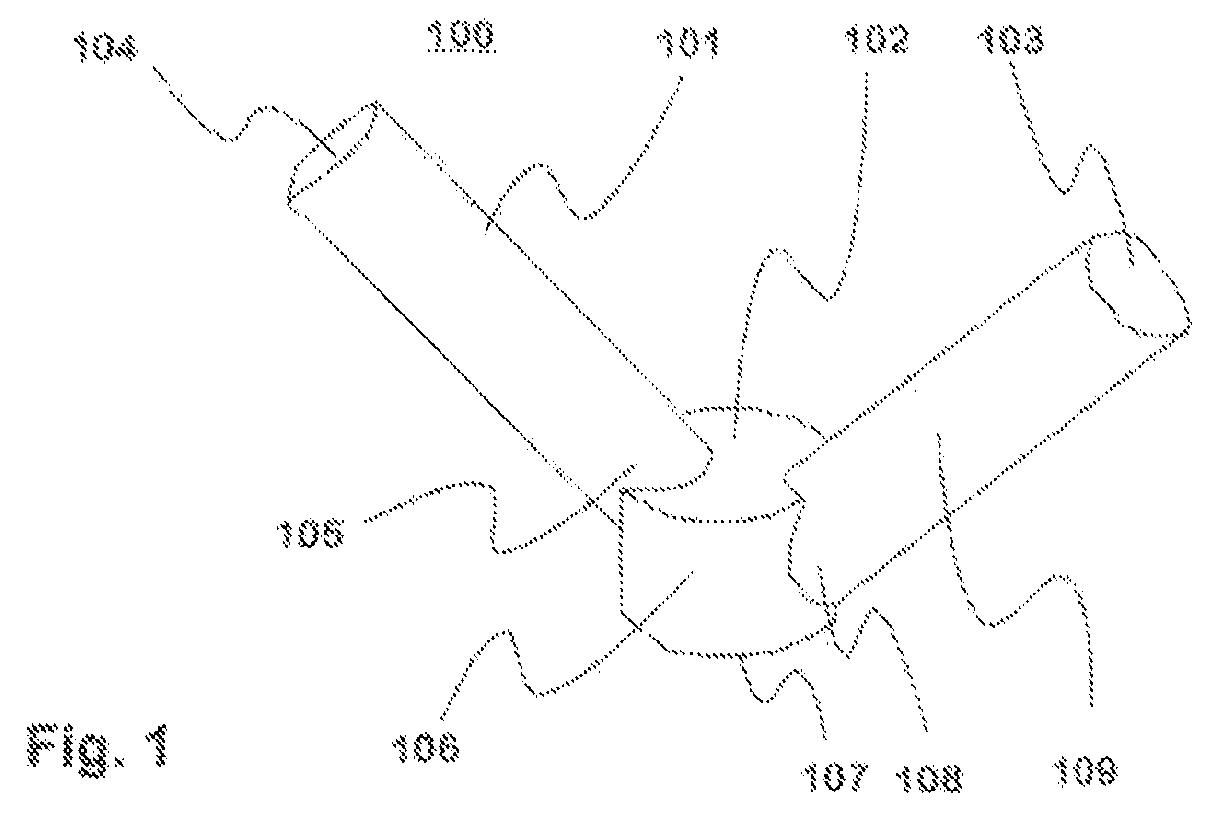
[0030]FIG. 1 shows an example of an inner conductor 100 of a resonator 100 according to the invention. The inner conductor 100 includes base 106, which is formed with a conductive material. In this example, the base portion 106 is a cylindrical structure having a first end 107 and a second end 102. The base portion 106 may, of course, be of some other shape, such as for example ...


PUM


Abstract

A resonator according to the invention includes an Inner conductor. The resonator has a easing comprising walls, a lid and a bottom shell within which there is a resonator cavity. The Inner conductor is in said resonator cavity. The Inner conductor is a conductive material formed with a base portion having a first end and a second end having a first end attached to a surface of the resonator cavity galvanically, in addition, the inner conductor has two or more elongate conductive materials forming resonator parts having a first end and a second end, and the resonator pasts first end is galvanically secured to the base portion at one end and the other end is galvanically separated from the resonator cavity inner surface. The characteristics of the resonator parts are selected so that each produces its own resonance width. These properties Include, for example, size, shape, orientation, material, and their different combinations.

Description

BACKGROUND OF THE INVENTION[0001]1. Field of the Invention[0002]The invention relates to the inner conductor of the resonator, the resonator comprises a casing, consisting of walls, lid and bottom of the casing resonator cavity in that the inner conductor is arranged to be located in said resonator, and into the resonator cavity, in a resonator cavity which has at least one inner conductor,[0003]2. Description of the Prior Art[0004]Cavity resonators commonly used for making the filters in telecommunications networks, in particular, when the transmitted signal power is relatively high This is because these losses are due to the small size of resonator filters, which means only a small efficiency signal fade. In addition, the response characteristics are well controllable and adjustable to most stringent specifications,[0005]Most of the filters and the filter pass band width of the space are intended to be fixed. In some of the filters the filter passband width is supposed to be const...

Claims


Application Information

Patent Timeline
Patent Type & Authority Applications(United States)
IPC IPC(8): H01P7/04
CPCH01P1/20H01P7/06H01P7/04H01P1/205
Inventor PUOSKARI, JUKKAPARI, PETRI
Owner INTEL CORP
Why Eureka
Try Eureka