Pedicle screw with electro-conductive coating or portion

a technology of electro-conductive coating and pedicle screw, which is applied in the field of medical devices, can solve the problems of not always the case, the relatively poor conductivity of titanium, and achieve the effect of reducing or eliminating the loss of curren

Inactive Publication Date: 2016-02-11
SMITH JEFFREY SCOTT
View PDF0 Cites 13 Cited by
  • Summary
  • Abstract
  • Description
  • Claims
  • Application Information

AI Technical Summary

Benefits of technology

[0010]By providing an electrically conductive coating or portion which conducts electrical energy better than the other portions of the pedicle screw, the coating or portion provides a sort of electrical “highway” that will help to focus the electrical energy applied to the pedicle screw into a particular direction. The coating or portion can be specifically configured so that this directional “highway” is oriented towards the presumed location of the nerve root, which would increase the accuracy of information obtained during neuromonitoring.
[0013]By way of example, the elongate electrically conductive portion may comprise a relatively narrow, elongate “strip” of the second material, e.g., disposed on or in one side of the shaft (e.g., on or in the side that is oriented towards the nerve root when the device is inserted into the pedicle). Such a strip of material may extend along the outside of the device, or a portion of it may be disposed internally. For example, in the case of a cannulated screw or tap, a portion of the electrically conductive portion could be placed inside the cannula of the device and then via a small passageway also coated with or otherwise provided with the second material, this upper portion of the electrically conductive portion could be connected to a patch of any desired shape or size on the outer surface of the screw (e.g., on the nerve root side, at the desired location between the distal and proximal ends). Such an embodiment may reduce or eliminate the loss of current as the electrical energy travels to the region of interest on the outside of the screw or tap device.

Problems solved by technology

For example, one problem with existing systems and methods is that titanium is a relatively poor conductor of electricity compared to other metals, such as gold or silver.
Such is not always the case.

Method used


Image

  • Pedicle screw with electro-conductive coating or portion
  • Pedicle screw with electro-conductive coating or portion
  • Pedicle screw with electro-conductive coating or portion

Examples


Embodiment Construction

I. Introduction

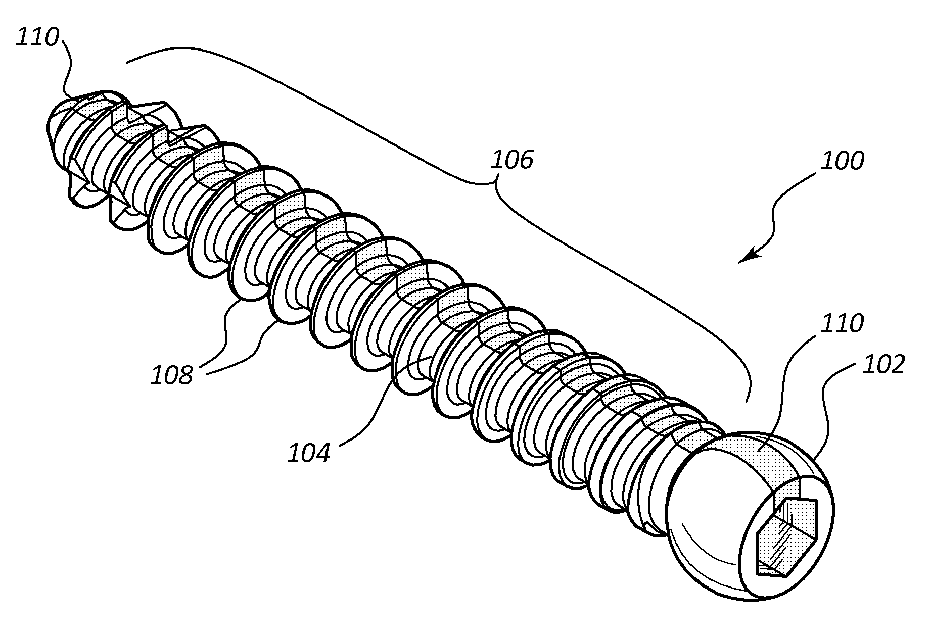
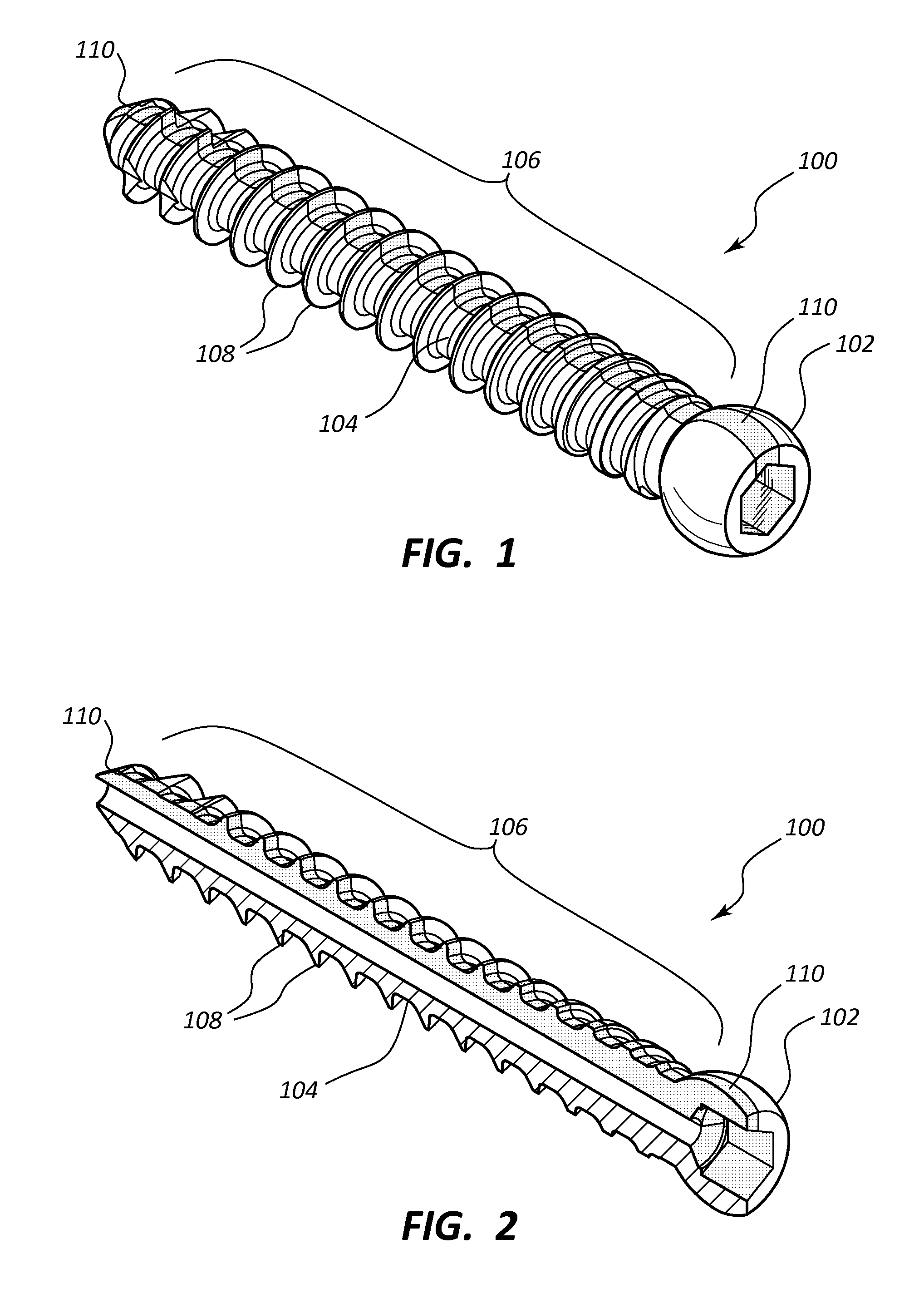
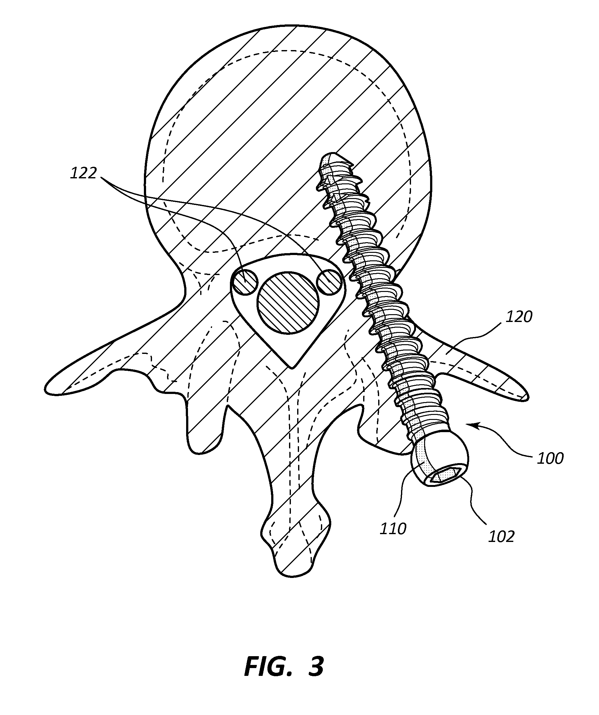
[0027]The proposed invention involves the application of a coating or otherwise providing a portion to a pedicle screw which preferentially channels electrical energy supplied by an electrical probe to the pedicle screw head during neuromonitoring. The coating or other portion provides a sort of electrical “highway” that helps to focus the electrical energy applied to the pedicle screw in a particular direction, towards the presumed location of the nerve root. As an alternative to placement of the electrically conductive portion in the pedicle screw itself, the coating or other portion could alternatively be placed within a tap that is used in preparing the pedicle for receipt of the pedicle screw (e.g., in forming the threaded structure in the pedicle bone into which the pedicle screw will then be placed). In such embodiments, the pedicle screw employed may then not necessarily include any such electrically conductive portion, as verifying the placement of the pedicl...


PUM


Abstract

A pedicle screw may include an electrically conductive portion formed from a material having a greater electrical conductivity than that of the base material from which the screw is formed. The electrically conductive portion preferentially channels electrical energy supplied by an electrical probe to a location of the electrically conductive portion facing the nerve root. The portion thus provides a sort of electrical highway that helps to focus the electrical energy applied to the pedicle screw in a particular direction, towards the presumed location of the nerve root. As an alternative to placement of the electrically conductive portion in the pedicle screw itself, the electrically conductive portion could be placed within a tap that is used in preparing the pedicle for receipt of the pedicle screw (e.g., in forming the threaded structure in the pedicle bone into which the pedicle screw will then be placed).

Description

CROSS-REFERENCE TO RELATED APPLICATIONS[0001]The present application claims the benefit under 35 USC §119(e) of U.S. Patent Application Ser. No. 62 / 034,420, filed Aug. 7, 2014 and entitled “APPLICATION OF AN ELECTRICALLY CONDUCTIVE COATING TO A PEDICLE SCREW”, the disclosure of which is incorporated by reference in its entirety.BACKGROUND OF THE INVENTION[0002]1. The Field of the Invention[0003]The present invention generally relates to medical devices and methods of use, particularly to pedicle screw systems and methods for their installation.[0004]2. The Relevant Technology[0005]Over the past several decades, spinal surgery has increasingly become an important option available to surgeons and patients in treating issues related to the spine. Because the spine generally provides support and movement for the body, a problem with the spine (e.g., a back disorder) can disrupt even the simplest life activities. In general, thousands of surgical fusions of the spine are performed each y...

Claims


Application Information

Patent Timeline
Patent Type & Authority Applications(United States)
IPC IPC(8): A61B17/86A61B17/70A61N1/05
CPCA61B17/866A61B17/7032A61B17/7076A61B17/7092A61B2017/90A61B17/8635A61N1/0558A61B2017/0003A61B17/8615A61B17/1655
Inventor SMITH, JEFFREY, SCOTT
Owner SMITH JEFFREY SCOTT
Why Eureka
Try Eureka