Rotor blade of a wind turbine

a technology of wind turbine and rotor blade, which is applied in the direction of liquid fuel engines, vessel construction, marine propulsion, etc., can solve the problems of large rotor blades that are difficult to transport, the width of the rotor blade in the root region of the rotor blade may also be at issue, and the length of the rotor blade is at issue, so as to achieve the effect of increasing the overall heating power

Inactive Publication Date: 2016-02-18
WOBBEN PROPERTIES GMBH
View PDF1 Cites 10 Cited by
  • Summary
  • Abstract
  • Description
  • Claims
  • Application Information

AI Technical Summary

Benefits of technology

[0015]Thus separate heating means are provided, which on the one hand are able to heat both the rotor blade nose and the rotor blade rear edge, however on the other hand are able to heat the rotor blade in a targeted and differentiated manner depending on the provided control. Thus it is optionally possible to heat only the rotor blade nose or only the rotor blade rear edge. Different heating strengths or different durations of heating may also be provided. In contrast to the use of only one heating means, not only can said heating be done in a

Problems solved by technology

Larger rotor blades are thereby often difficult to transport on the road.
On the one hand, the length of the rotor blades is at issue, but on the other hand, the width of the rotor blades in the root region thereof may also be at issue, at least in the case of modern rotor blades, the greatest width of which is in the region of the root of the rotor blade.
During operation, the rotor blades are exposed to the wind accordingly and depending on the temperature and humidity of the wind, this

Method used


Image

  • Rotor blade of a wind turbine
  • Rotor blade of a wind turbine
  • Rotor blade of a wind turbine

Examples


Embodiment Construction

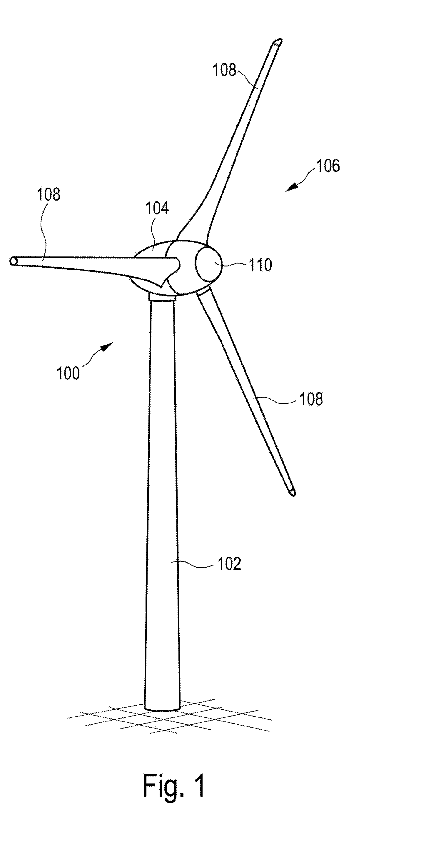
[0049]FIG. 1 shows a wind turbine 100 with a tower 102 and nacelle 104. A rotor 106 with three rotor blades 108 and a spinner 110 is located on the nacelle 104. When in operation, the rotor 106 is brought to a rotating movement by the wind and thereby drives a generator in the nacelle 104.

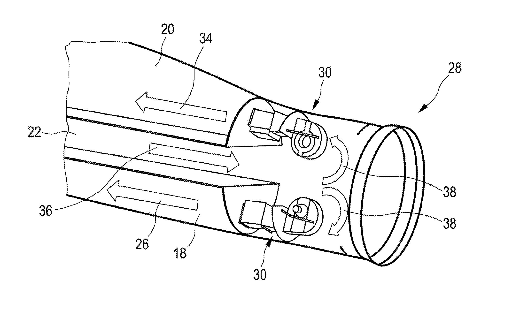
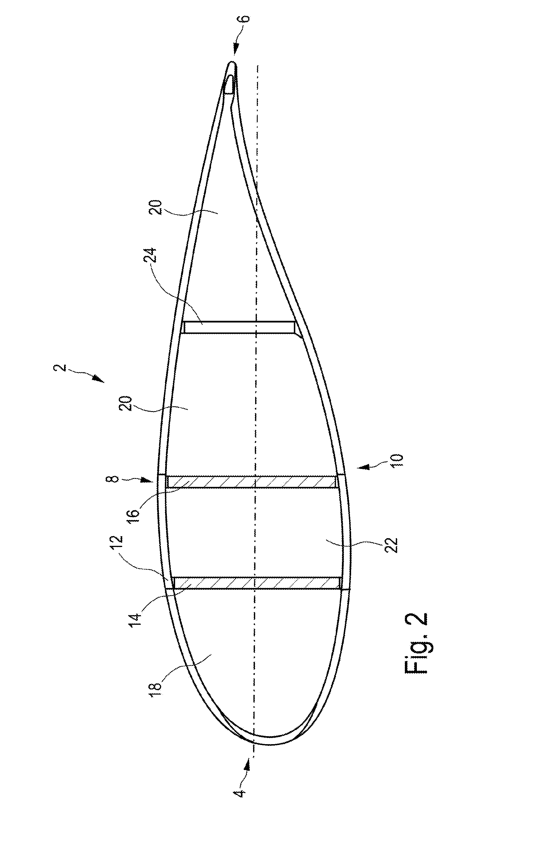
[0050]FIG. 2 shows a cross-section of a rotor blade 2 having a rotor blade nose 4 and a rotor blade rear edge 6. The illustrated cross-section shows a profile of the rotor blade 2 approximately in the middle region thereof with respect to the longitudinal direction of the rotor blade. Moreover, the profile has a suction side 8 and a pressure side 10. A first and a second stiffening partition 14 or 16 respectively inter alia are provided in order to stiffen the outer shell 12. Both stiffening partitions 14 and 16 are hatched and thereby represented as cut elements, and they form continuous walls and divide the rotor blade 2, at least in the region shown, into a first cavity 18, which faces the rotor...


PUM

PropertyMeasurementUnit
Fractionaaaaaaaaaa
Fractionaaaaaaaaaa
Lengthaaaaaaaaaa

Abstract

The invention relates to a rotor blade of a wind turbine, having a rotor blade nose, a rotor blade rear edge, a rotor blade root region for the attachment of the rotor blade to a hub of the wind turbine, a rotor blade tip, wherein the rotor blade extends from the rotor blade root region along a longitudinal direction to the rotor blade tip and the rotor blade internally comprises at least a first cavity facing the rotor blade nose and a second cavity facing the rotor blade rear edge, and the first cavity is heated by a first, and the second cavity is heated by a second heating means, in order to heat the rotor blade nose or the rotor blade rear edge respectively. In addition, it is suggested that the rotor blade have a rear edge segment disposed in the region of the rotor blade rear edge up to the root region, wherein the rear edge segment is designed having several parts having at least two segment sections.

Description

BACKGROUND[0001]1. Technical Field[0002]The present invention relates to a rotor blade of a wind turbine as well as to a wind turbine. Moreover, the present invention relates to a method of manufacturing a rotor blade and the present invention relates to a method of installing a wind turbine. Moreover, the present invention relates to a rear edge segment of a rotor blade of a wind turbine.[0003]2. Description of the Related Art[0004]Wind turbines are generally known and FIG. 1 schematically shows a wind turbine. The rotor blades are an important component of a wind turbine. These blades transform kinetic energy from the wind into kinetic energy for driving a generator.[0005]In order to increase the efficiency of wind turbines, these wind turbines or wind power installations are increasingly being built larger. This has also led to the development and the design of larger rotor blades. Larger rotor blades are thereby often difficult to transport on the road. On the one hand, the leng...

Claims


Application Information

Patent Timeline
IPC IPC(8): F03D1/06F03D1/00
CPCF03D1/0675F03D11/0025F03D1/001F03D1/0658F03D1/065F05B2240/30F03D80/40F03D13/10Y02E10/72F03D9/22F03D1/0633
Inventor PAWLS, TORSTENMIDDELSTADT, FALKSCHULZE, THOMASRUBNER, FLORIAN
Owner WOBBEN PROPERTIES GMBH
Why Eureka
Try Eureka