
Dual outlet burner and method

a burner and outlet technology, applied in the direction of combustion regulation, combustion types, lighting and heating apparatuses, etc., can solve the problems of generating significant amounts of nox emissions, not sufficiently addressing nox formation and reduction at the burner, etc., to reduce nox emissions and increase efficiency.

Inactive Publication Date: 2016-02-18
ECLIPSE
View PDF10 Cites 3 Cited by
  • Summary
  • Abstract
  • Description
  • Claims
  • Application Information

AI Technical Summary

Benefits of technology

The present disclosure describes a burner with two separate gas jets that can be controlled independently using two valves to adjust flame shape and lower NOx emissions. The burner has a swirling device to further widen flame shape and increase efficiency over traditional gas burners. A moveable intermediate tube is used as the flow adjustment valve to control the velocity of the inner gas jet. The terms "gas" and "gaseous fuel" refer to fuel in gas form such as natural gas and liquid petroleum gas commonly used in industrial process burners.

Problems solved by technology

As a result, furnace and flame temperatures tend to be high, resulting in the generation of significant amounts of NOx emissions.
Although some of these controls have been partially effective at controlling NOx emissions, they may not sufficiently address NOx formation and reduction at the burner.

Method used


Image

  • Dual outlet burner and method
  • Dual outlet burner and method
  • Dual outlet burner and method

Examples


Embodiment Construction

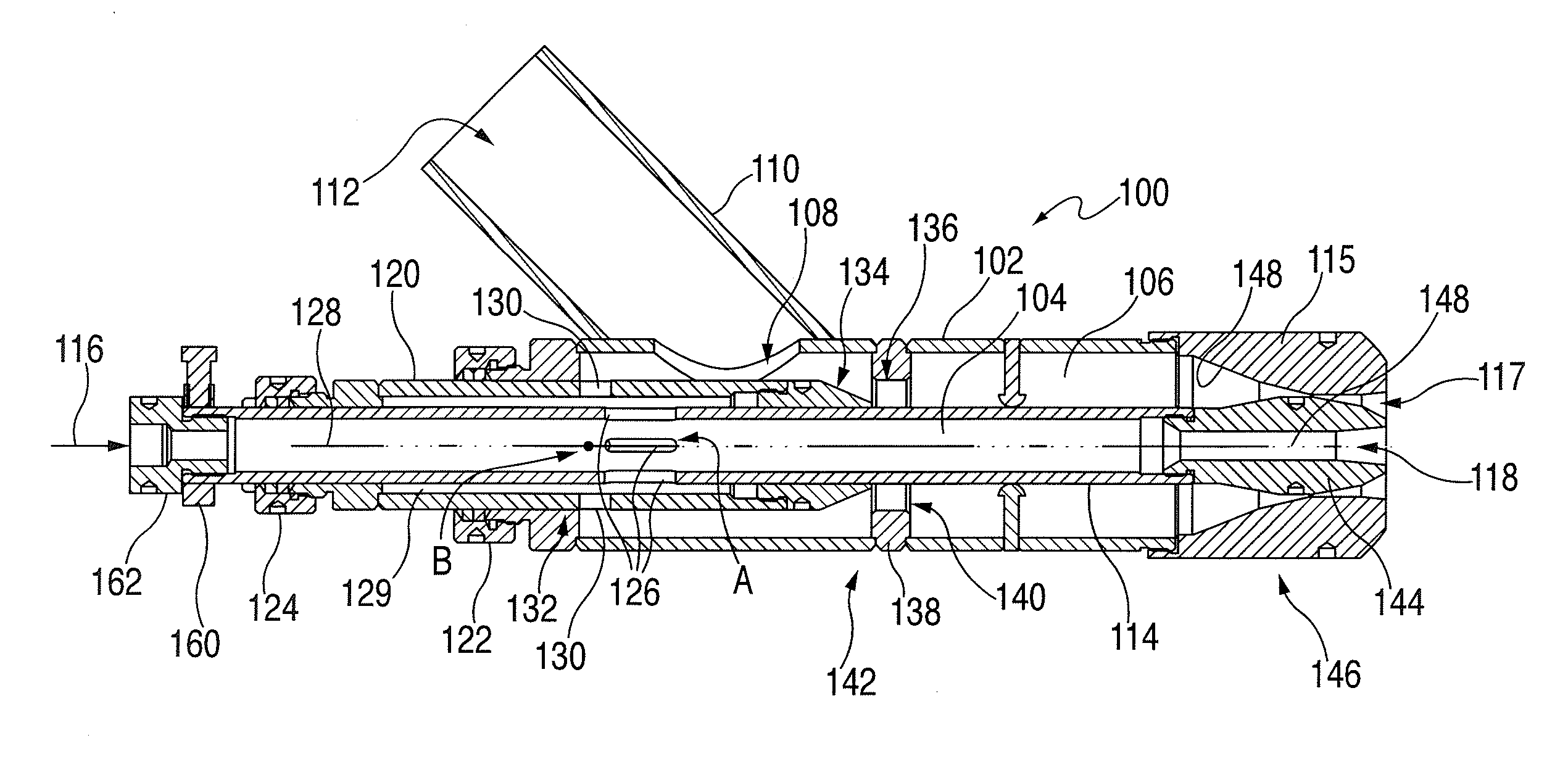
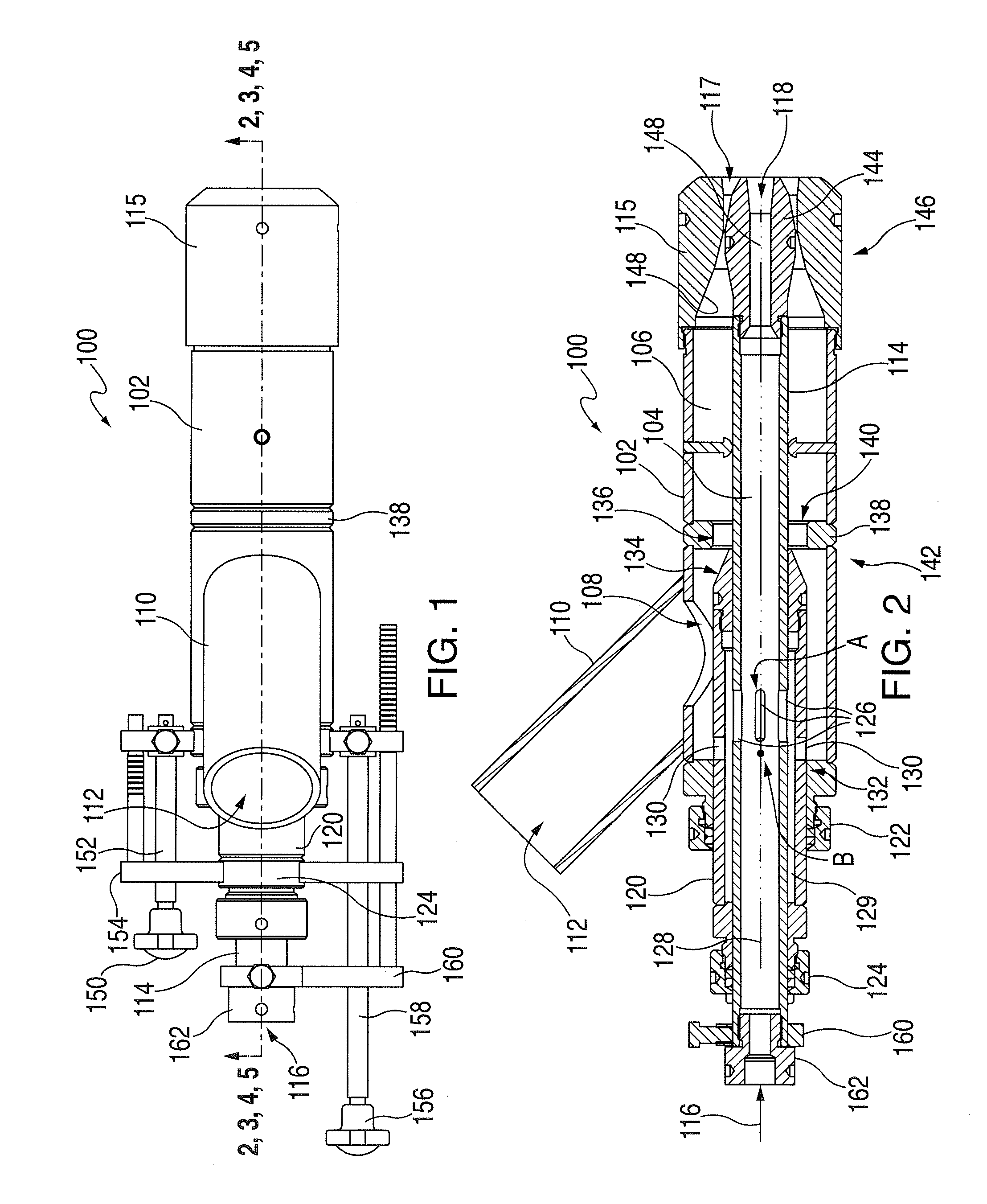
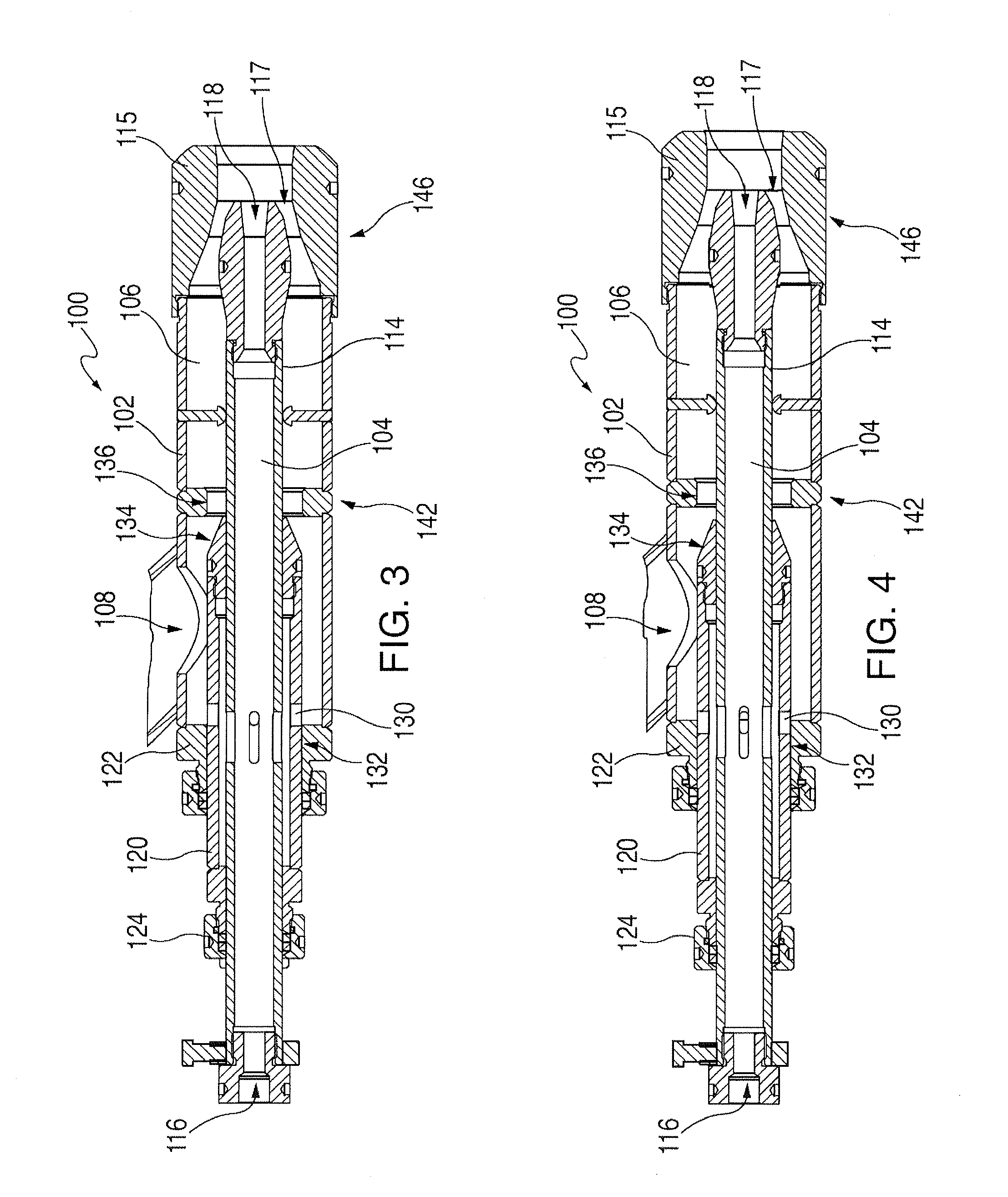
[0011]Reference will now be made to the drawings wherein like elements are designated by like reference numbers in the various views. FIG. 1 illustrates an outline view of a burner 100 from a top perspective, and FIGS. 2-5 illustrate fragmentary views of the burner 100 in various operating positions. As shown in these illustrations, the burner 100 includes a generally hollow tubular casing or outer tube 102, which encloses an inner plenum 104 and an outer plenum 106 (FIG. 2). The outer tube 102 forms an opening 108 that constitutes a main fuel inlet opening. Fuel, for example, a gaseous fuel, is provided through a conduit 110 having an opening 112 in fluid communication with a fuel source. The outer plenum 106 forms an outer nozzle opening 117 at an end. The outer nozzle opening 117 in the illustrated embodiment is within a converging nozzle end-piece 115 and surrounds an inner nozzle opening 118.

[0012]In the illustrated embodiment, an inner tube 114 extends generally concentrically...


PUM


Abstract

A burner includes a casing that encloses an outer plenum, the casing forming a fuel inlet and an outer nozzle at its end. An inner tube extends generally concentrically through the outer plenum and forms an inner plenum such that the casing encloses the outer plenum and the inner plenum. The inner tube forms an inner nozzle at its end. The inner nozzle is disposed generally concentrically with respect to the outer nozzle. A valve arrangement adjusts a fuel velocity separately through each of the outer nozzle and the inner nozzle to shape a flame created when the fuel is provided in an oxidant rich environment.

Description

CROSS-REFERENCE TO RELATED APPLICATIONS[0001]This patent application claims the benefit of U.S. Provisional Patent Application No. 62 / 037,708, filed Aug. 15, 2014, which is incorporated herein in its entirety by this reference.BACKGROUND[0002]Industrial furnaces, such as regenerative glass melting furnaces, operate at high temperatures, typically in the range of about 2400-3000° F., to promote furnace and process thermal efficiency. As a result, furnace and flame temperatures tend to be high, resulting in the generation of significant amounts of NOx emissions.[0003]Efforts to control NOx emissions have resulted in the development of various NOx control technologies. Such technologies inhibit NOx formation by modifying flame stoichiometry and the overall combustion process. Exemplary NOx control technologies include oxygen-enriched air staging, in which oxygen-enriched air is introduced in stages into the combustion process, exhaust gas recirculation, in which exhaust gas is introduc...

Claims


Application Information

Patent Timeline
Patent Type & Authority Applications(United States)
IPC IPC(8): F23N1/00F23D14/56F23D14/58F23D14/62F23D14/84
CPCF23N1/002F23D14/62F23D14/84F23N1/007F23D14/56F23D14/58F23C2900/07021F23D14/20Y02E20/34
Inventor ANDERSON, SCOTT
Owner ECLIPSE
Learn More