
Pwm rectifier for motor drive connected to electric storage device

a technology of pwm rectifier and electric storage device, which is applied in the direction of motor/generator/converter stopper, motor/dynamo-electric converter control, electric/dynamo-electric converter starter, etc., can solve the problem of electric power peak, ac power supply capacity tends to become large, and power supply capacity on the ac power supply side is inevitably large, so as to reduce the power supply capacity

Active Publication Date: 2016-02-18
FANUC LTD
View PDF5 Cites 3 Cited by
  • Summary
  • Abstract
  • Description
  • Claims
  • Application Information

AI Technical Summary

Benefits of technology

The technical effect of this patent is to provide a PWM rectifier for a motor drive that can reduce the electric power peak during acceleration and deceleration of the motor, and also decrease the power supply capacity on the AC power supply side.

Problems solved by technology

In an acceleration or deceleration control of a motor with a motor drive unit, an output or regeneration with large amount of AC power is required to an AC power supply, which leads an occurrence of an electric power peak.
However, according to the design in consideration of the electric power peak which occurs at the time of the acceleration and deceleration of the motor, a power supply capacity is inevitably large compared to a case in a simple design in consideration of the average power of a motor drive unit.
When addressing the electric power peak which occurs at the time of accelerating or decelerating the motor as described above, the power supply capacity on AC power supply side tends to become large.
Therefore, an electric storage device is charged to the condition before the motor acceleration, and whereby the regenerative energy generated at the time of motor deceleration cannot be stored in the electric storage device.
However, the DC voltage command is required to be set by trial and error for each operation pattern of a motor, which is not practical.

Method used


Image

  • Pwm rectifier for motor drive connected to electric storage device
  • Pwm rectifier for motor drive connected to electric storage device
  • Pwm rectifier for motor drive connected to electric storage device

Examples


first embodiment

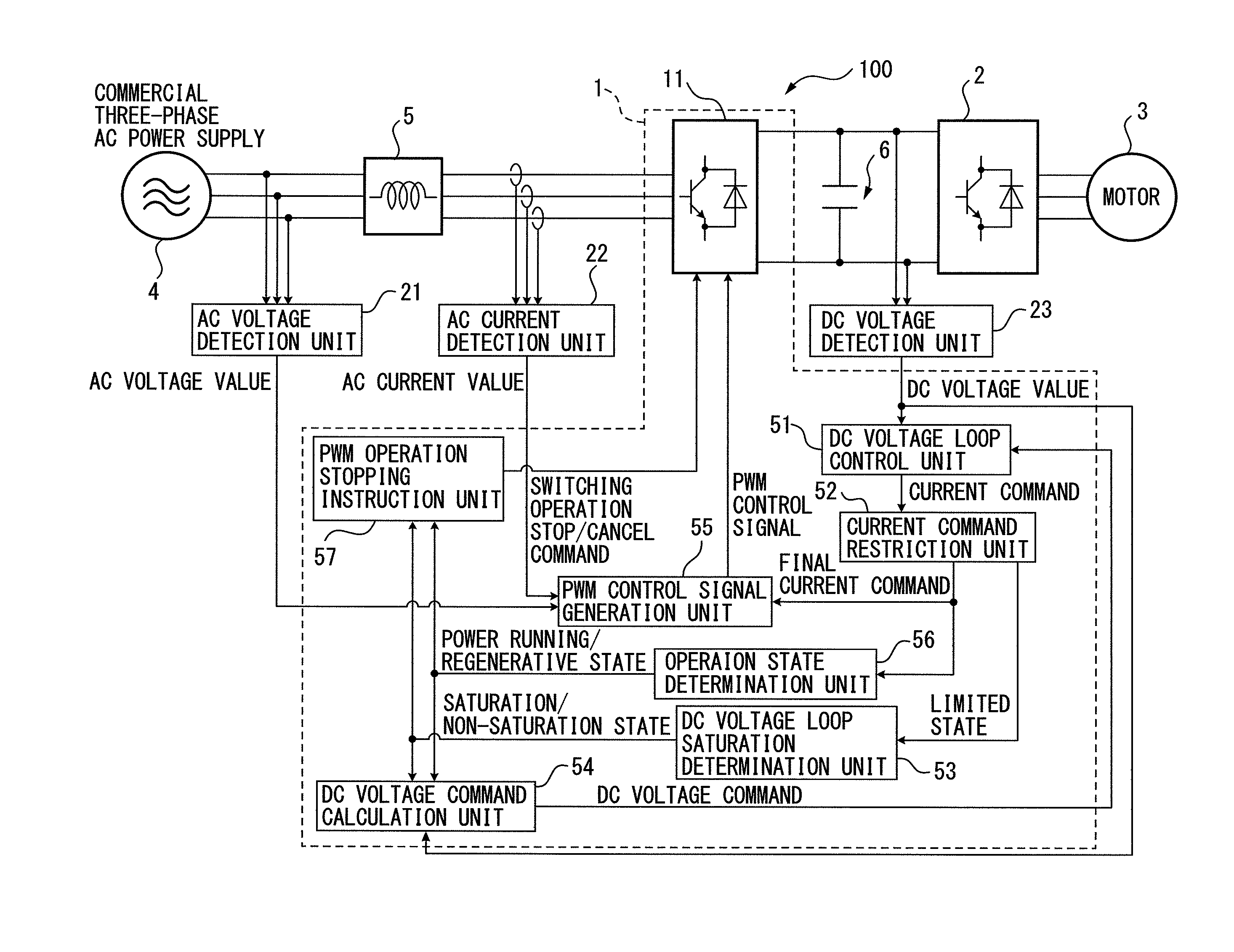
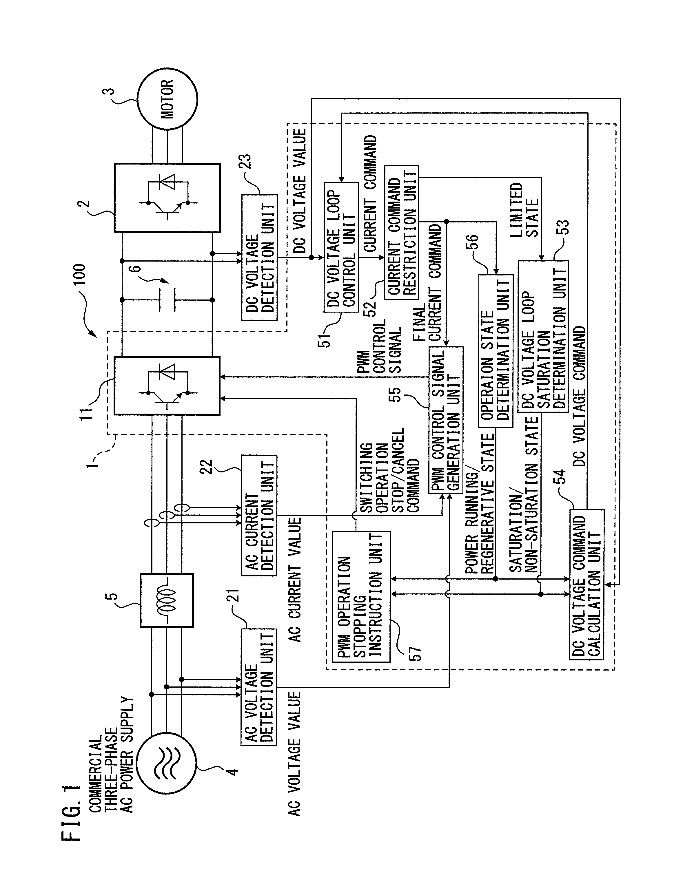
[0062]The PWM rectifier 1 is connected, in the motor control device 100, to the DC side of the inverter 2 which performs the power conversion between the DC power and the AC power which is the drive power or regenerative power of the motor 3, through the electric storage device 6 which can store the DC power. The PWM rectifier 1 includes a main circuit unit 11, a DC voltage loop control unit 51, a current command restriction unit 52, a DC voltage loop saturation determination unit 53, a DC voltage command calculation unit 54, a PWM control signal generation unit 55, an operation state determination unit 56, and a PWM operation stopping instruction unit 57.

[0063]In the motor drive unit 100 which temporally converts the AC power input from the AC power supply side into the DC power and then further into the AC power to use the converted AC power as the drive power for the motor, the AC voltage value and the AC current value on the AC power supply side, and the DC voltage value at the...

second embodiment

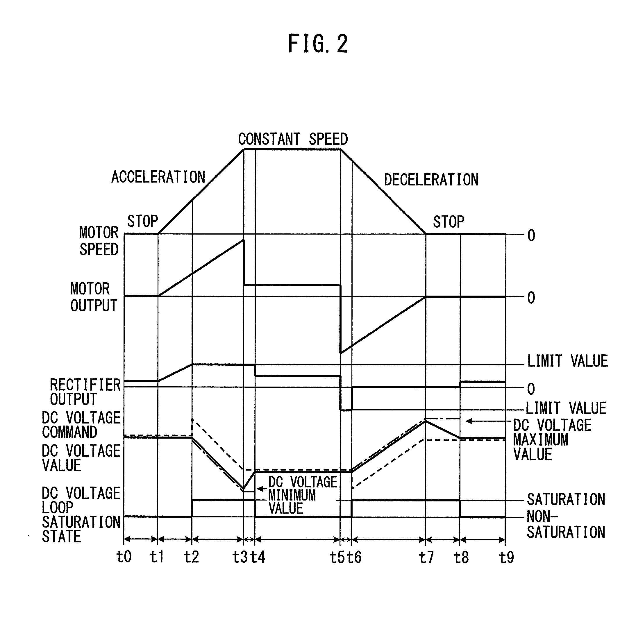
[0093]FIG. 5 is a principle block diagram of a PWM rectifier according to a FIG. 6 is a timing chart schematically illustrating an operation of the PWM rectifier illustrated in FIG. 5. Note that FIG. 6 illustrates a “motor speed”, a “motor output”, a “rectifier output”, “DC voltage command and DC voltage value”, and “the state of the DC voltage loop control unit” from the top. A dashed line illustrates the DC voltage command and a dashed-dotted line illustrates the minimum or maximum value of the DC voltage value.

[0094]The second embodiment further develops the PWM operation stopping instruction unit 57 in the PWM rectifier 1 according to the first embodiment illustrated in FIG. 1. In other words, according to the second embodiment, a PWM operation stopping instruction unit 57 cancels the stop of the switching operation in the main circuit unit 11 when the DC voltage value detected by the DC voltage detection unit 23 exceeds a predetermined value under a condition in which the DC v...

third embodiment

[0104]FIG. 7 is a principle block diagram of a PWM rectifier according to a FIG. 8 is a timing chart schematically illustrating an operation of the PWM rectifier illustrated in FIG. 7. Note that FIG. 8 illustrates a “motor speed”, a “motor output”, a “rectifier output”, “DC voltage command and DC voltage value”, and “the state of the DC voltage loop control unit” from the top. A dashed line illustrates the DC voltage command and a dashed-dotted line illustrates the minimum or maximum value of the DC voltage value.

[0105]The third embodiment further develops the current command restriction unit 52 in the PWM rectifier 1 according to the first embodiment illustrated in FIG. 1, or the current command restriction unit 52 in the PWM rectifier 1 according to the second embodiment illustrated in FIG. 5. Note that FIG. 7 illustrates a case in which a limit value change unit 61 is provided in the current command restriction unit 52 in the PWM rectifier 1 according to the second embodiment il...


PUM


Abstract

A PWM rectifier includes a main circuit unit which performs a power conversion on the basis of a PWM control signal, a DC voltage loop control unit which generates a current command, a current command restriction unit which sets, when an absolute value of the current command exceeds a limit value, the limit value as a final current command, and otherwise sets the current command as the final current command, a DC voltage loop saturation determination unit which determines a saturation state when the final current command is set to the limit value and otherwise determines as a non-saturation state, a DC voltage command calculation unit which changes the DC voltage command into a value obtained by adding an offset to a minimum or maximum value of the DC voltage value, and a PWM control signal generation unit which generates the PWM control signal from the final current command.

Description

BACKGROUND OF THE INVENTION[0001]1. Field of the Invention[0002]The present invention relates to a PWM rectifier for a motor drive, which controls a switching element using a PWM signal to convert three-phase AC power into DC power, and in particular relates to a PWM rectifier connected, through an electric storage device which can store DC power, to the DC side of an inverter which performs a power conversion between DC power and AC power being drive power or regenerative power of a motor.[0003]2. Description of the Related Art[0004]In a motor drive unit for driving motors used in machine tools, industrial machines, forming machines, injection molding machines, or various kinds of robots, DC power temporarily converted from AC power which is input from an AC power supply side is further converted to AC power. The converted AC power is used as drive power of a motor provided for each drive axis. The motor drive unit includes: a rectifier for outputting DC power by rectifying AC powe...

Claims


Application Information

Patent Timeline
Patent Type & Authority Applications(United States)
IPC IPC(8): H02P27/08
CPCH02P27/08
Inventor NIWA, MASAKAZUYAMAMOTO, KENTA
Owner FANUC LTD
Learn More