Coupling and rotor shaft for molten metal devices

a technology of molten metal devices and couplings, which is applied in the direction of charging manipulation, lighting and heating apparatuses, furnaces, etc., can solve the problem of rotor shafts being prone to breakag

Active Publication Date: 2016-02-25
MOLTEN METAL EQUIP INNOVIATIONS LLC
View PDF6 Cites 58 Cited by
  • Summary
  • Abstract
  • Description
  • Claims
  • Application Information

AI Technical Summary

Benefits of technology

[0015]The present invention helps to alleviate the afore-mentioned problems by providing a coupling and rotor shaft for use in a molten metal pump, a molten metal rotary degasser or a molten metal scrap melter. The coupling has a collar with a cavity open at the bottom and a protrusion extending out of the cavity. The protrusion is preferably threaded along at least part of its length, wherein the threaded portion(s) are preferably outside of the cavity.

Problems solved by technology

A problem with the couplings, however, is that by applying driving force to the rotor shaft the rotor shaft tends to break at the location where the force is being applied.

Method used


Image

  • Coupling and rotor shaft for molten metal devices
  • Coupling and rotor shaft for molten metal devices
  • Coupling and rotor shaft for molten metal devices

Examples


Embodiment Construction

[0029]For any device described herein, any of the components that contact the molten metal are preferably formed by a material that can withstand the molten metal environment. Preferred materials are oxidation-resistant graphite and ceramics, such as silicon carbide. Oxidation-resistant graphite is most preferred because of its relatively low cost and ease of manufacturing.

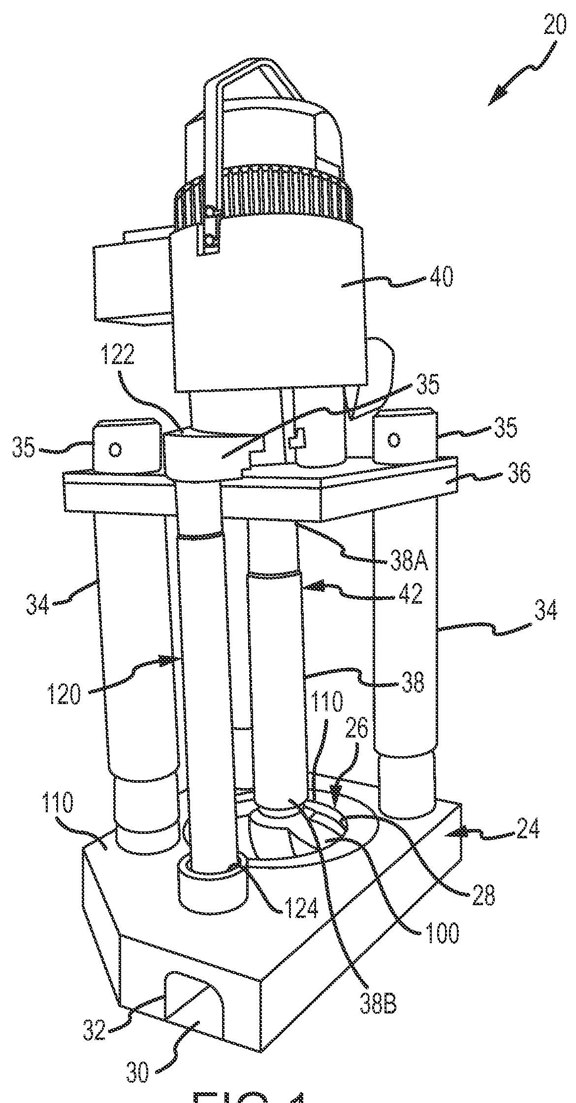
[0030]Referring now to the drawing where the purpose is to illustrate and describe different embodiments of the invention, and not to limit same, FIG. 1 shows a molten metal pump 20 in accordance with an aspect of the present invention. Pump 20 is designed for operation in any environment in which molten metal is to be pumped or otherwise conveyed. Pump 20 can be any structure or device for pumping or otherwise conveying molten metal, such as the tangential-discharge pump disclosed in U.S. Pat. No. 5,203,681 to Cooper, or an axial pump having an axial, rather than tangential, discharge. Pump 20 has a pump base 24 ...


PUM

PropertyMeasurementUnit
diameteraaaaaaaaaa
diameteraaaaaaaaaa
diameteraaaaaaaaaa

Abstract

A coupling has an opening and a protrusion extending downward from the opening. The protrusion has threads that are preferably positioned outside of the opening. A rotor shaft that connects to the coupling has an internal bore with threads that receives and retains the protrusion, such as by a threaded connection between the two, so the protrusion applies driving force to the shaft.

Description

CROSS REFERENCE TO RELATED APPLICATION[0001]This application is a non-provisional of and claims priority to U.S. Provisional Application Ser. No. 62 / 020,332 entitled “Coupling and Rotor Shaft for Molten Metal Devices, filed on Jul. 2, 2014, the contents of which are incorporated herein in its entirety for all purposes.FIELD OF THE INVENTION[0002]The invention relates to couplings and rotor shafts that may be used in various devices, such as pumps, degassers and scrap melters used in molten metal.BACKGROUND OF THE INVENTION[0003]As used herein, the term “molten metal” means any metal or combination of metals in liquid form, such as aluminum, copper, iron, zinc and alloys thereof. The term “gas” means any gas or combination of gases, including argon, nitrogen, chlorine, fluorine, freon, and helium, that are released into molten metal.[0004]Known molten-metal pumps include a pump base (also called a housing or casing), one or more inlets (an inlet being an opening in the housing to all...

Claims


Application Information

Patent Timeline
Patent Type & Authority Applications(United States)
IPC IPC(8): F16D1/02F16C3/02F27D3/14F27D17/00F27D99/00
CPCF16D1/02F16C3/02F27D2099/0083F27D17/002F27D99/00F27D3/14F04D29/20C22B9/00C22B7/003F16D1/10F16D2001/102F04D7/065F27D27/005F27D3/16Y02P10/20
Inventor COOPER, PAUL, V.
Owner MOLTEN METAL EQUIP INNOVIATIONS LLC
Why Eureka
Try Eureka