Avian detection systems and methods

a detection system and avian technology, applied in the field of avian detection systems and methods, can solve the problems of high labor intensity and inherently inaccurate, difficulty in reliably determining the number of birds and the species of such birds in an area, and the injuries of avians that leave, so as to facilitate rapid and accurate determination of moving objects, the effect of cost-effective and reliabl

Active Publication Date: 2016-02-25
IDENTIFLIGHT INT LLC
View PDF0 Cites 45 Cited by
  • Summary
  • Abstract
  • Description
  • Claims
  • Application Information

AI Technical Summary

Benefits of technology

[0008]The disclosed systems and methods provide detection of a flying avian for large airspace volumes in a manner that is both cost-effective and reliable. The systems are completely scalable, being compatible with any number of imagers and systems, dependent on the application of interest, with larger areas covered by increasing the number of systems. Integration of specially configured imagers with efficient algorithms facilitate rapid and accurate determination of moving objects along with whether such moving objects may represent an avian of interest warranting further analysis for moving objects within a user-defined airspace. A first wide field of view imager assists with simultaneously

Problems solved by technology

This is a reflection that human-based detection of flying avians requires intensive training to be able to properly identify avians and species thereof, is highly labor intensive and is inherently inaccurate.
One challenge for accurately assessing the risk of wind turbine collision by a flying avian is the difficulty in reliably determining the number of birds and the species of such birds in an area of a turbine or a to-be-located turbine.
This has numerous disadvantages, including not accounting for cluster fatalities, injured avians that leave the immediate area or are removed by scavengers, and the challenge associated with reliably and consistently locating carcasses.
A fundamental limitation of that system is the reported detection efficiency of 86-96% for a distance of only 150 m from the wind turbine, with an efficiency that falls off with increasing distances.
Those systems, however, require bulky and expensive radar equipment and are not suited to distinguishing be

Method used


Image

  • Avian detection systems and methods
  • Avian detection systems and methods
  • Avian detection systems and methods

Examples


example 1

Detection Methods

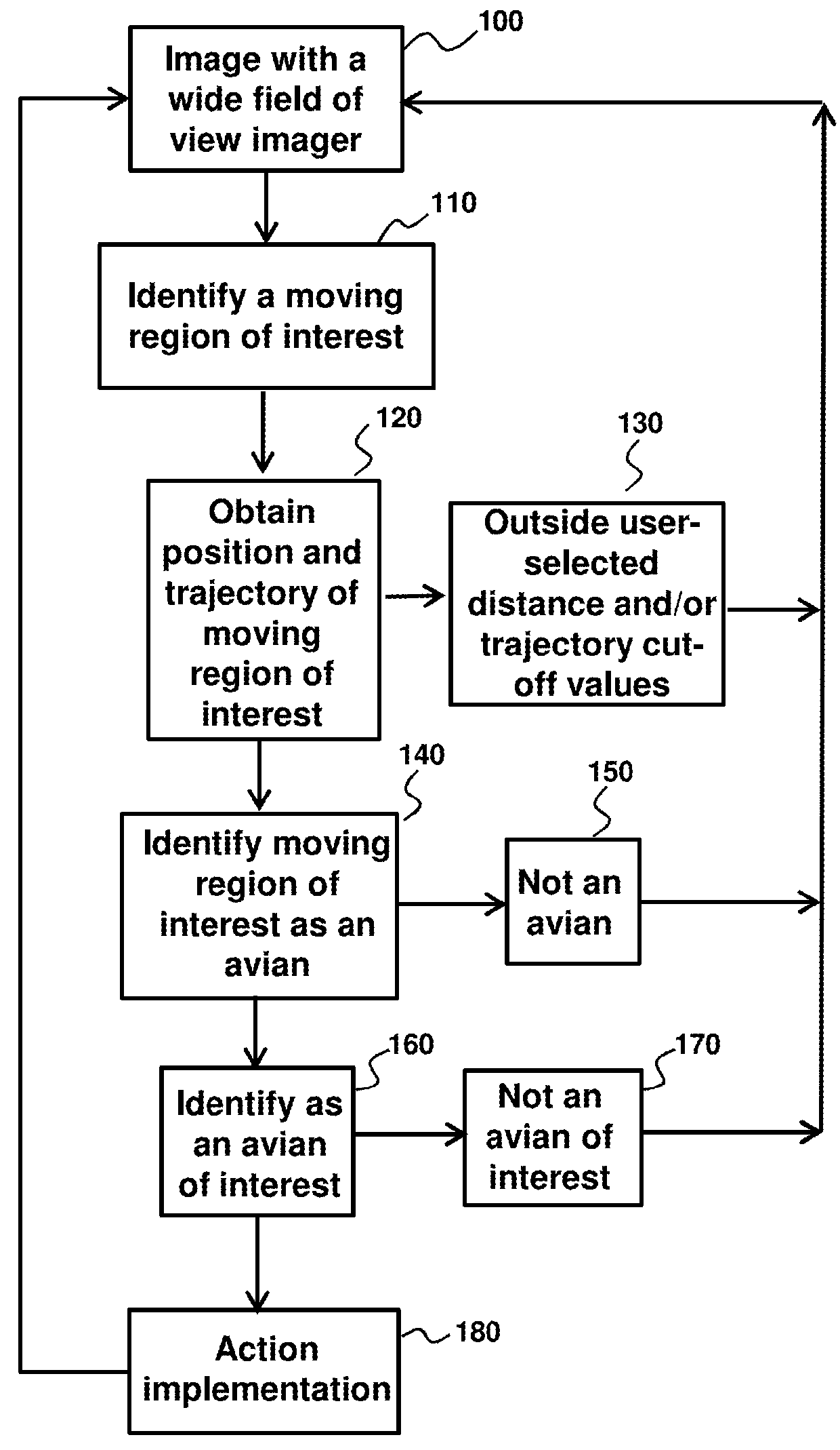
[0120]Referring to FIG. 1, an overall flow process of a general strategy for detecting a flying avian in an airspace is by imaging at least a portion of or all the airspace surrounding the system with a wide field of view imager 100. For example, in an unobstructed airspace a single wide field of view imager having a wide-angle optical system (see, e.g., U.S. Pat. No. 8,284,258) may image an entire hemisphere. Alternatively, for imagers that cover less than an entire hemisphere of surrounding airspace, a plurality of imagers may be used to provide complete hemispherical coverage. This may be particularly useful in situations where there is a physical obstruction, such as with a building, tower, tree, wind turbine nacelle, or the like. In such situations, more than one imager may be strategically located to provide multiple fields of view, that when combined, provide complete or substantially complete hemispherical coverage.

[0121]A wide field of view imager or imager...

example 2

Hemispherical Coverage—Single and Plurality of Imaging Systems

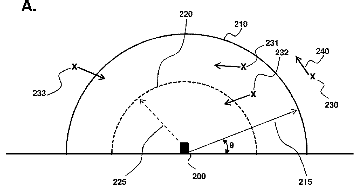
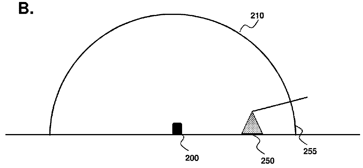
[0131]Referring to FIGS. 2-3, the systems and methods provided herein provide good coverage over a well-defined airspace. FIG. 2A is a side view schematic of an avian detection system 200 for detecting a flying avian (230231232233) in an airspace 210. In this example, airspace 210 is hemispherical and is defined by a distance 215. In contrast, FIG. 2B (top panel) illustrates an embodiment where there is an obstacle 250 that results in a volume of airspace that may be partially optically blocked 255. The obstacle may be an artificial object such as a building, tower or vehicle, or naturally occurring such as a hill, tree or boulder. Accordingly, the airspace may be described herein as being “substantially hemispherical” in recognition that unless the surrounding ground is flat and without obstruction, deviations from true hemispherical is expected. FIG. 2B further emphasizes that the term “substantially hemispherical” refe...

example 3

Pattern Recognition Algorithms

[0137]The systems and methods provided herein are compatible with any number of pattern recognition algorithms known in the art, including the process summarized in FIG. 1. Referring to FIG. 4, a more detailed description of an algorithm is provided herein. The first imager identifies an output of a subset of pixels from the field of view 400, such as an array of intensity values. From the output of the subset of pixels, one or more threshold identification attributes are identified 410 and used to determine whether further analysis is warranted 420. The threshold identification attributes may be a signature that is characteristic of a flying avian. The threshold identification attribute may be a characteristic of the pixel arrangement, intensity, distance, time evolution (e.g., position, distance and / or trajectory). A common aspect of the threshold identification attribute(s) is that it provides the capability of quickly and reliably determining whethe...


PUM


Abstract

Provided herein are detection systems and related for detecting moving objects in an airspace surrounding the detection system. In an aspect, the moving object is a flying animal and the detection system comprises a first imager and a second imager that determines position of the moving object and for moving objects within a user selected distance from the system the system determines whether the moving object is a flying animal, such as a bird or bat. The systems and methods are compatible with wind turbines to identify avian(s) of interest in airspace around wind turbines and, if necessary, take action to minimize avian strike by a wind turbine blade.

Description

CROSS-REFERENCE TO RELATED APPLICATIONS[0001]This application claims the benefit of U.S. Pat. App. No. 62 / 040,018, filed Aug. 21, 2014, which is specifically incorporated by reference in its entirety.BACKGROUND OF INVENTION[0002]There is an interest and need in the art for reliable and robust detection of flying avians. Avian detection systems have many applications, ranging from avian counts, classification and / or identification in a specific geographical location, to deterrence and counter-measure systems for aviation and wind production systems. A common objective of such systems is the replacement of subjective and inaccurate human-based counts with an automated and reliable detection system. This is a reflection that human-based detection of flying avians requires intensive training to be able to properly identify avians and species thereof, is highly labor intensive and is inherently inaccurate.[0003]One specific application of bird detection systems is for wind energy generat...

Claims


Application Information

Patent Timeline
IPC IPC(8): F03D1/06F03D7/02F03D7/04G06T7/00G06T7/20G06T7/40G06V10/147G06V20/00H04N5/225H04N5/232H04N5/247H04N13/239
CPCG06K9/6267G06K2009/4666H04N5/23296H04N5/247G06K9/4604G06T7/0085G06K9/4652G06T7/408G06T7/20H04N13/0239G06K9/6201H04N5/2252G06T7/0044F03D1/06F03D7/0264F03D7/0276F03D7/042F03D11/0041F03D11/0091G06T2207/30241H04N5/23238F03D7/02F05B2270/8041F03D80/00F03D17/00G06T7/74G06T7/13G06T7/90H04N13/239G06V40/20G06V20/00G06V10/147Y02E10/72F03D80/10G06F18/00G06F18/24H04N23/51H04N23/69H04N23/90H04N23/698
Inventor JORQUERA, CARLOSCOPPAGE, AARONDESALVO, JASONLUTTRELL, RYANLUTTRELL, JASON
Owner IDENTIFLIGHT INT LLC
Why Eureka
Try Eureka