Wireless Power Transfer System and Method

a wireless power transfer and wireless technology, applied in the direction of transformer/inductance details, circuit arrangements, inductances, etc., can solve the problems of low efficiency and high cost, and achieve the effect of improving the efficiency of the wireless power transfer system

Active Publication Date: 2016-02-25
NUVOLTA TECH
View PDF0 Cites 64 Cited by
  • Summary
  • Abstract
  • Description
  • Claims
  • Application Information

AI Technical Summary

Benefits of technology

[0012]These and other problems are generally solved or circumvented, and technical advantages are generally achiev

Problems solved by technology

As such, the system shown in FIG. 1 is a complex

Method used


Image

  • Wireless Power Transfer System and Method
  • Wireless Power Transfer System and Method
  • Wireless Power Transfer System and Method

Examples


Embodiment Construction

[0041]The making and using of the presently preferred embodiments are discussed in detail below. It should be appreciated, however, that the present invention provides many applicable inventive concepts that can be embodied in a wide variety of specific contexts. The specific embodiments discussed are merely illustrative of specific ways to make and use the invention, and do not limit the scope of the invention.

[0042]The present invention will be described with respect to preferred embodiments in a specific context, namely a wireless power transfer system having a plurality of variable capacitance networks. The invention may also be applied, however, to a variety of other power systems. Hereinafter, various embodiments will be explained in detail with reference to the accompanying drawings.

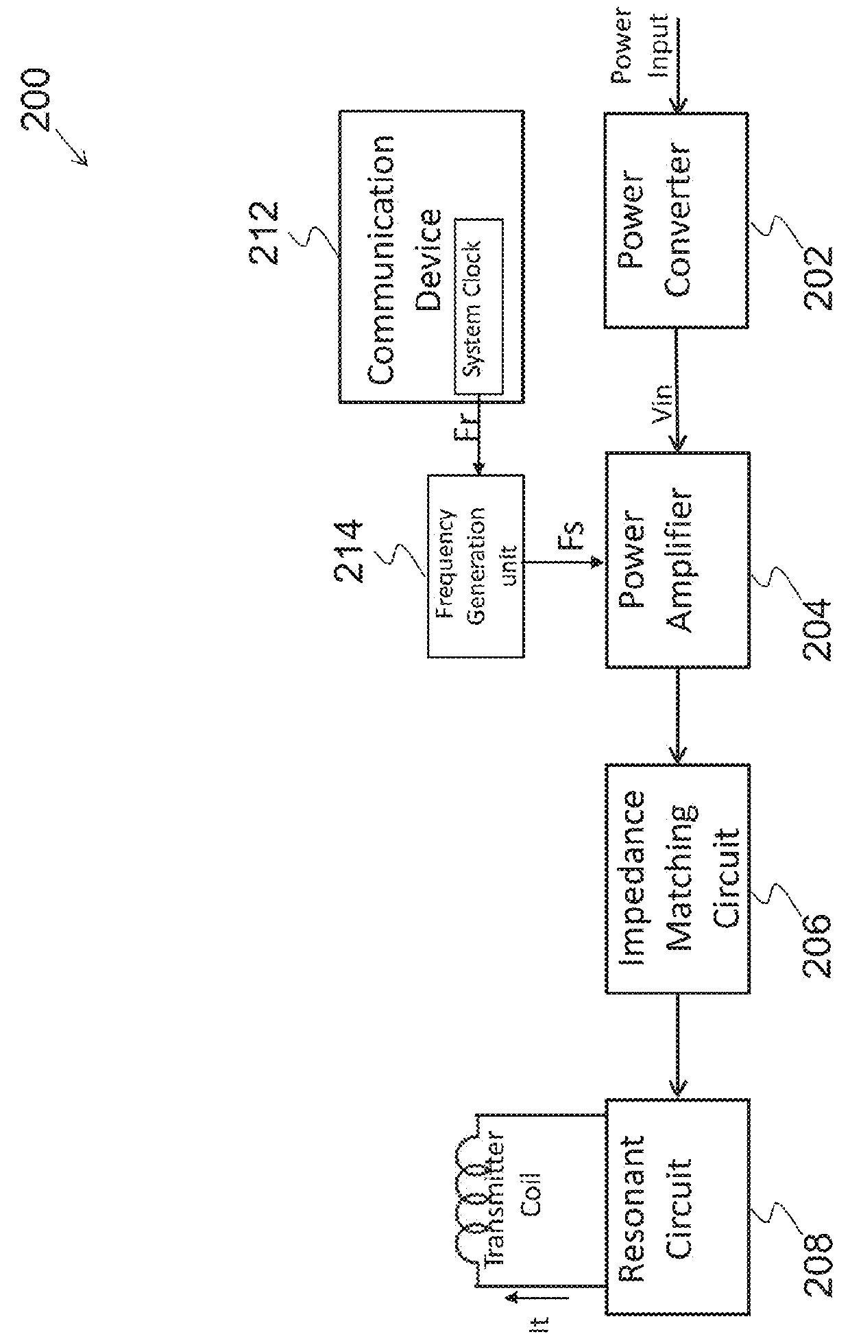
[0043]FIG. 2 illustrates a block diagram of a first implementation of a power transmitter of a wireless power transfer system in accordance with various embodiments of the present disclosure. The ...


PUM


Abstract

A system comprises a primary switch network coupled to a power source, wherein the primary switch network comprises a plurality of power switches, a primary resonant tank coupled to the plurality of power switches, wherein a resonant capacitor of the primary resonant tank is formed by a first variable capacitance network, and wherein the first variable capacitance network is modulated to improve soft switching of the plurality of power switches through reducing a voltage level and a current level of a switch at a turn-on instant and a primary coil coupled to the primary resonant tank.

Description

[0001]This application claims the benefit of U.S. Provisional Application No. 62 / 041,161, filed on Aug. 25, 2014, entitled “Cost-effective High Performance Wireless Power Transfer Techniques,” which application is hereby incorporated herein by reference.TECHNICAL FIELD[0002]The present invention relates to high performance power supplies, and, in particular embodiments, to a wireless power transfer system.BACKGROUND[0003]As technologies further advance, wireless power transfer (WPT) has emerged as an efficient and convenient mechanism for powering or charging battery based mobile devices such as mobile phones, tablet PCs, digital cameras, MP3 players and / or the like. A wireless power transfer system typically comprises a primary side transmitter and a secondary side receiver. The primary side transmitter is magnetically coupled to the secondary side receiver through a magnetic coupling. The magnetic coupling may be implemented as a loosely coupled transformer having a primary side c...

Claims


Application Information

Patent Timeline
IPC IPC(8): H02J5/00
CPCH02J5/005H02J50/80H02J50/12H02J7/025H02J50/10
Inventor MAO, HENGCHUN
Owner NUVOLTA TECH
Why Eureka
Try Eureka