Magnetomotive Probe System And Method Of Use Thereof

Inactive Publication Date: 2016-03-03
NKIJ ENGINEERING AB
View PDF7 Cites 0 Cited by
  • Summary
  • Abstract
  • Description
  • Claims
  • Application Information

AI Technical Summary

Benefits of technology

The patent text describes various technical improvements related to the field of nanoparticle analysis and magnetomotive imaging. These improvements include increased accuracy in identifying the concentration of nanoparticles in a material, as well as improved accuracy in analyzing the properties of magnetic materials. Additionally, the patent describes a compact and easy-to-use system for performing magnetomotive imaging.

Problems solved by technology

A problem with such previous techniques is that the displacement amplitude of the nanoparticle-laden regions is higher closer to the tip, and the resulting image data therefore gives misleading information about the nanoparticle concentration.
This inevitable leads to problems in providing accurate analysis of the properties of the material or tissue in which the nanoparticles has been collected, e.g. in the situation where the nanoparticles have been labeled with tumor- or tissue specific targeting agents.
The information available for e.g. detecting cancer in tissue therefore becomes flawed.
Problems with prior art thus includes insufficient accuracy in detecting these targeting nanoparticles, and consequently insufficient accuracy in detecting, resolving and analyzing the material which the nanoparticles targets and binds.
Further problems with prior art is that the tissue which is analyzed is affected by the analyzing equipment, for example by heat, which also decreases the possibilities for performing a complete analysis of the tissue.
Thus another problem with prior art is the unsuitability of these setups for applications in humans or larger animals due to restrictions or limitations in positioning the various components such as the magnet in relation to the ultrasound transducer.
Problems with prior art, if at all possible to implement, may accordingly lead to reduced patient safety, more time consuming and expensive diagnosis, and less possibilities for an individualized treatment in the patient care.

Method used


Image

  • Magnetomotive Probe System And Method Of Use Thereof
  • Magnetomotive Probe System And Method Of Use Thereof
  • Magnetomotive Probe System And Method Of Use Thereof

Examples


Embodiment Construction

[0034]Specific embodiments of the invention will now be described with reference to the accompanying drawings. This invention may, however, be embodied in many different forms and should not be construed as limited to the embodiments set forth herein; rather, these embodiments are provided so that this disclosure will be thorough and complete, and will fully convey the scope of the invention to those skilled in the art. The terminology used in the detailed description of the embodiments illustrated in the accompanying drawings is not intended to be limiting of the invention. In the drawings, like numbers refer to like elements.

[0035]The following description focuses on an embodiment of the present invention applicable to a probe assembly for magnetomotive imaging. However, it will be appreciated that the invention is not limited to this application but may be applied to many other fields and applications.

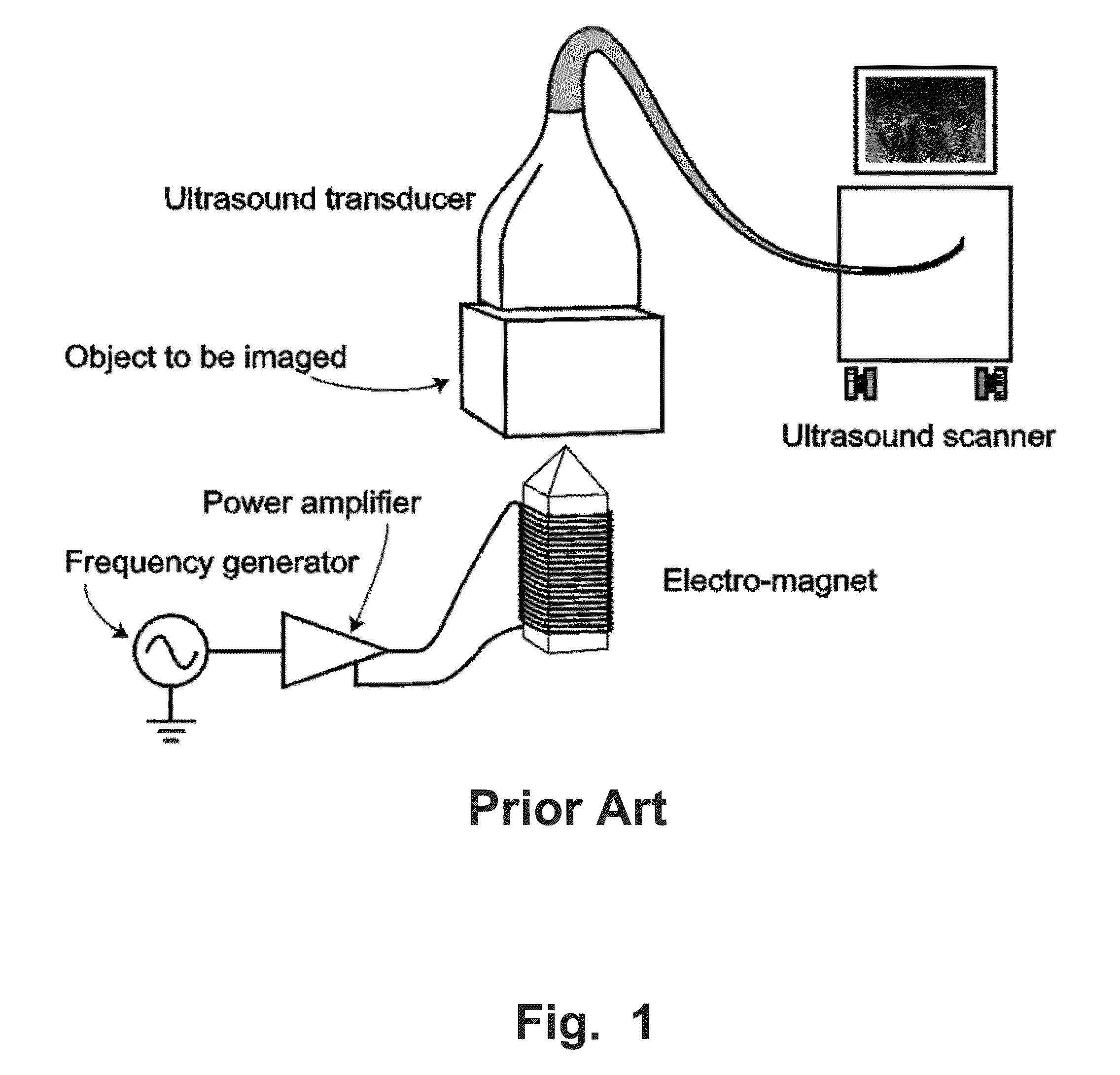
[0036]FIG. 1 shows a prior art magnetomotive imaging setup as discussed in the ...


PUM


Abstract

A magnetomotive imaging probe system is disclosed comprising a movable probe, a magnet arranged on the probe, and an ultra sound transducer, wherein the magnet is arranged to generate a time-varying magnetic field (T) at an imaging plane (304) of the ultrasound transducer, distally of the ultra sound transducer and the probe, when the probe has proximal first position adjacent the ultra sound transducer.

Description

FIELD OF THE INVENTION[0001]This invention pertains in general to the field of magnetomotive imaging. More particularly the invention relates to a magnetomotive imaging probe system, a magnetomotive imaging probe assembly, and a method of magnetomotive imaging with such imaging probe system or assembly.BACKGROUND OF THE INVENTION[0002]Magnetomotive imaging is a new imaging technique where superparamagnetic iron oxide nanoparticles can be used as ultrasound contrast agents. The main idea of this imaging technique is the application of a time-varying magnetic field (pulsed or sinusoidal) to the volume where the nanoparticles are deposited. The magnetic field induces movement of the particles and thereby the surrounding tissue. Previous techniques, such as disclosed in Evertsson, M. et al, IEEE, Transactions on ultrasonic, ferroelectrics, and frequency control, vol. 60, no. 3, 1 Mar. 2013, pages 481-491, that has been used to create the time-varying magnetic field has been employing an...

Claims


Application Information

Patent Timeline
IPC IPC(8): A61B8/08A61B8/00
CPCA61B8/4209A61B8/481A61B8/54A61B8/4455A61B8/4483A61B5/0515
Inventor CINTHIO, MAGNUSEVERTSSON, MARIAJANSSON, TOMASPERSSON, HANS, W.OLSSON, FREDRIKFREDRIKSSON, SARAH
Owner NKIJ ENGINEERING AB
Why Eureka
Try Eureka