
Applying apparatus

a technology of applying apparatus and gas exhausting, which is applied in the direction of soldering apparatus, separation processes, manufacturing tools, etc., can solve the problems of reducing the productivity of the applying apparatus and polluting the exhaust pipe, and achieve the effect of efficient exhausting of gas and increasing the flow rate of flux liquid

Active Publication Date: 2016-03-03
FUJITSU GENERAL LTD
View PDF8 Cites 5 Cited by
  • Summary
  • Abstract
  • Description
  • Claims
  • Application Information

AI Technical Summary

Benefits of technology

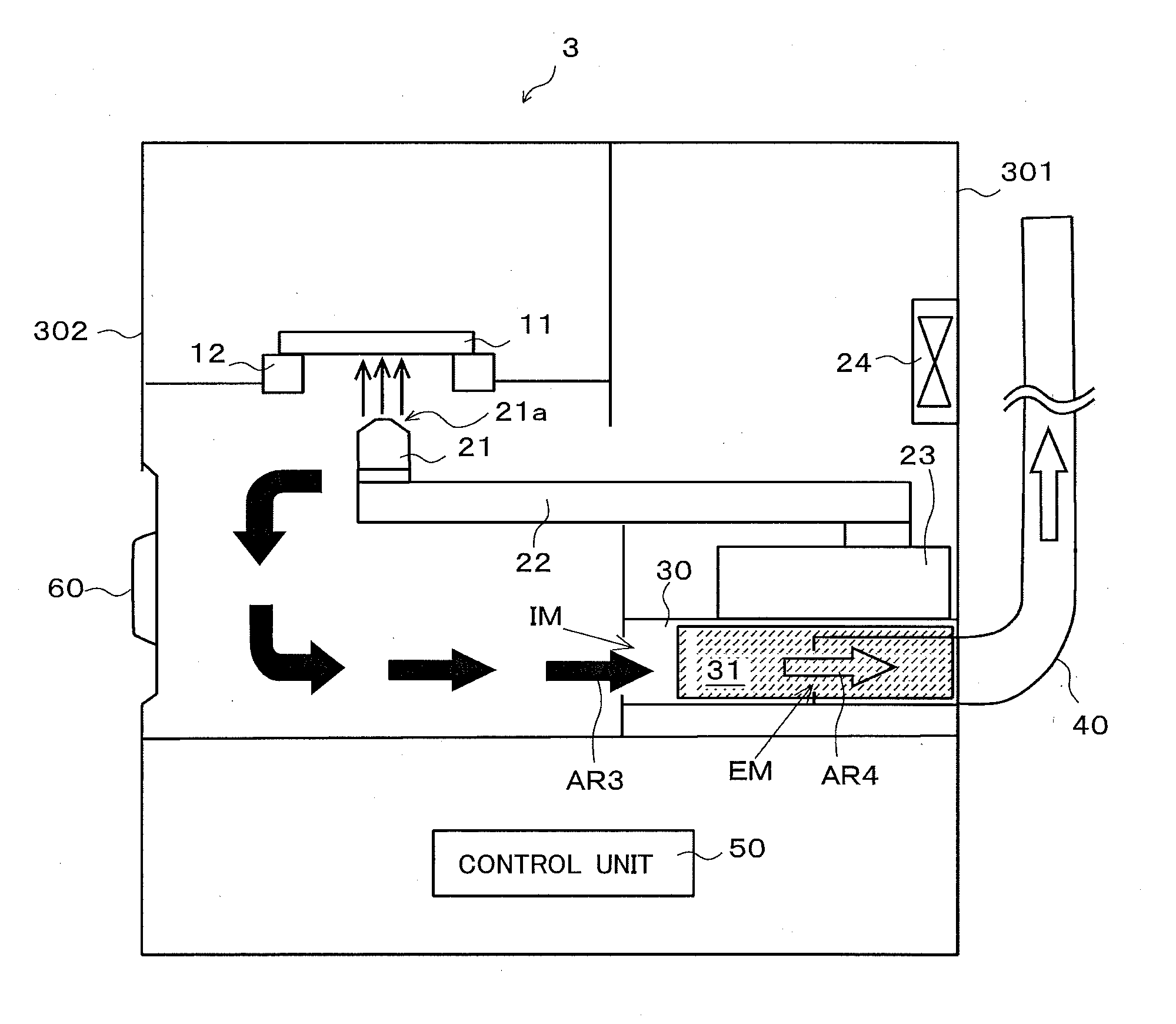
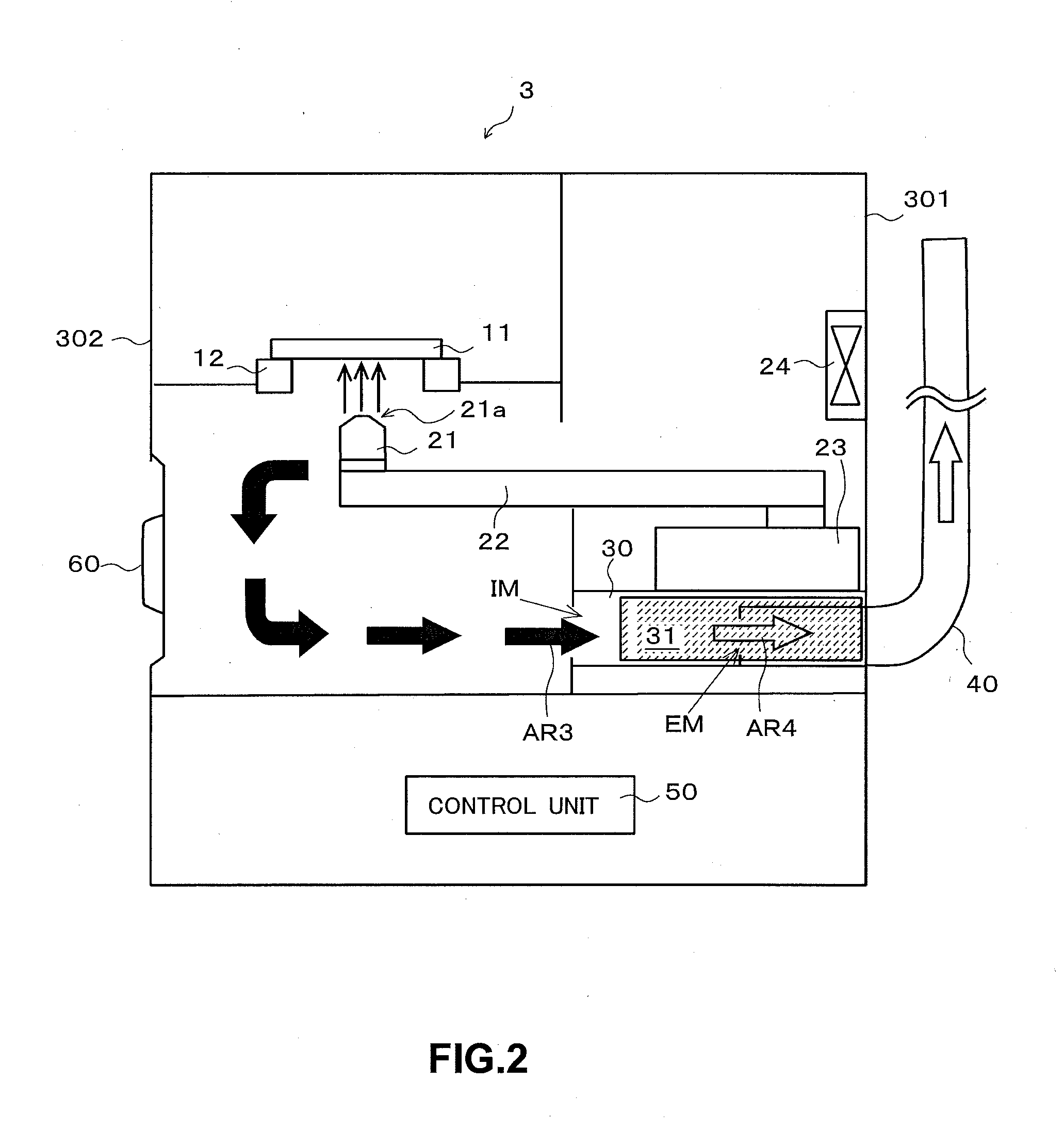
The invention is an applying apparatus that can filter flux liquid efficiently without reducing productivity. The apparatus has a filtering unit that can be easily detached in a way that allows other apparatuses to be placed next to it without interrupting the operation. The width of the first chamber of the intake and exhaust unit is made smaller to increase the flow rate of the flux liquid before filtering, and the width of the second chamber is made larger to efficiently exhaust the filtered gas through the exhaust port. Overall, the apparatus provides a simple method for exchanging the filter without stopping the operation.

Problems solved by technology

If the applying apparatus exhausts the sprayed flux without performing any process on an exhaust pipe connected to the applying apparatus, the flux base material is attached to the inside of the exhaust pipe, thereby polluting the exhaust pipe.
As a result, the productivity of the applying apparatus is reduced.

Method used


Image

  • Applying apparatus
  • Applying apparatus
  • Applying apparatus

Examples


first embodiment

1. First Embodiment

1-1. Summary of Applying System

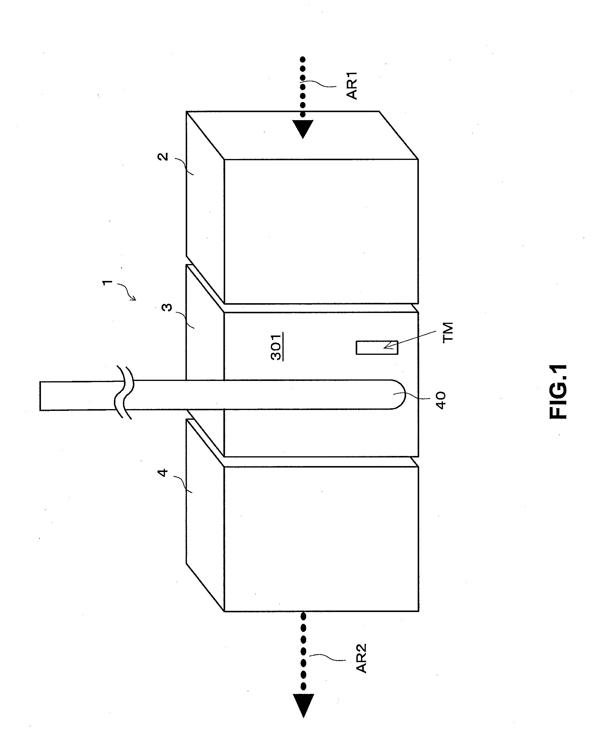
[0024]FIG. 1 schematically shows an applying system 1 according to a first embodiment. The applying system 1 mainly includes an assembling apparatus 2, a flux applying apparatus 3, and a soldering apparatus 4.

[0025]This applying system 1 solders electronic components placed on a printed circuit board. Specifically, a printed circuit board is conveyed to the assembling apparatus 2 in the direction of an arrow AR1. The conveyed printed circuit board passes through the flux applying apparatus 3 and the soldering apparatus 4 and is conveyed in the direction of an arrow AR2. That is, the printed circuit board on which electronic components have been soldered is conveyed. The applying system 1 manufactures an electronic circuit of the printed circuit board on which electronic components have been soldered in this way.

[0026]Since the printed circuit board is conveyed to the apparatuses sequentially in the applying system 1 as described abov...


PUM

PropertyMeasurementUnit
Lengthaaaaaaaaaa
Widthaaaaaaaaaa

Abstract

An applying apparatus that applies a flux liquid includes: a nozzle from which the flux liquid is injected; and an intake and exhaust unit that sucks the flux liquid injected from the nozzle through an intake port and exhausts a gas through an exhaust port. The intake and exhaust unit has a filtering unit that filters the flux liquid sucked through the intake port and through which the gas passes before the gas reaches the exhaust port. The filtering unit is movably provided within the intake and exhaust unit so that when installing / removing the filtering unit with respect to the intake and exhaust unit, the filtering unit moves in a direction substantially parallel to a direction in which the flux liquid is sucked through the intake port and in which the gas is exhausted through the exhaust port.

Description

BACKGROUND OF THE INVENTION[0001]1. Field of the Invention[0002]The present invention relates to a technique for exhausting a gas filtered by a filter.[0003]2. Description of the Background Art[0004]Generally, an electronic circuit is manufactured by placing electronic components on a printed circuit board and securing the electronic components using soldering. As a pre-process of the soldering, a flux liquid is applied to the printed circuit board. The flux liquid is created by diluting a flux base material with a diluent such as IPA (isopropyl alcohol). The flux liquid is applied in order to, for example, remove an oxide film on the surface of the printed circuit board to be soldered.[0005]As an applying apparatus that applies such a flux liquid, there is a known applying apparatus that injects the flux liquid from a nozzle to apply the flux liquid to a printed circuit. When the flux liquid is injected from the nozzle, the flux liquid is applied to the printed circuit board and th...

Claims


Application Information

Patent Timeline
IPC IPC(8): B01D46/00B05B12/16B05B14/00B05B14/30B05B16/00H05K3/34H05K13/04
CPCB01D46/0041H05K3/3457H05K13/0465B23K3/082B23K1/0016B23K1/008B23K1/203H05K3/3489H05K2203/0126H05K2203/081H05K2203/1581B23K2101/42
Inventor YAMAKAWA, TOMIHIRO
Owner FUJITSU GENERAL LTD
Learn More