Mobile robot

a robot and mobile technology, applied in the field of mobile robots, can solve the problems of inability to operate correctly, lack of random bounce navigation schemes, and inability to accurately locate the floor, so as to improve the responsiveness of adjustments, reduce the power provided to each light source, and prolong the battery life of the robot

Inactive Publication Date: 2016-03-03
DYSON TECH LTD
View PDF11 Cites 30 Cited by
  • Summary
  • Abstract
  • Description
  • Claims
  • Application Information

AI Technical Summary

Benefits of technology

[0017]The level of illumination provided by each of the light sources may be adjusted by increasing and decreasing the power provided to each of the light sources. This allows the power provided to each light source to be reduced when the light source is not required to provide a significant level of illumination. This efficient use of power can extend the battery life of the robot.
[0018]The level of illumination provided by each of the light sources may be independently adjusted in response to a control signal sent to the vision system by a control system. The control system may comprise a simultaneous localisation and mapping (SLAM) unit. As a result, the system that is responsible for navigation on the robot has direct control over the level of illumination provided by the light sources. This can improve the responsiveness of the adjustments made to the level of illumination in response to navigational requirements of the robot.
[0019]The camera may be a panoramic annular lens (PAL) camera. This allows the robot to capture images that provide a compl

Problems solved by technology

Unfortunately, these random bounce navigation schemes have been found to be lacking, and often large areas of the floor that should be cleaned will be completely missed.
However, the SLAM system can only function correctly provided it is able to detect enough features within the images captured by the vision system.
As such, it has been found that some robots struggle to successfully navigate in rooms that have low-light conditions or where the images captured by the vision system suffer from poor contrast.
Some robots are therefore restricted to navigating during the day when there is sufficient ambient l

Method used


Image

  • Mobile robot
  • Mobile robot
  • Mobile robot

Examples


Embodiment Construction

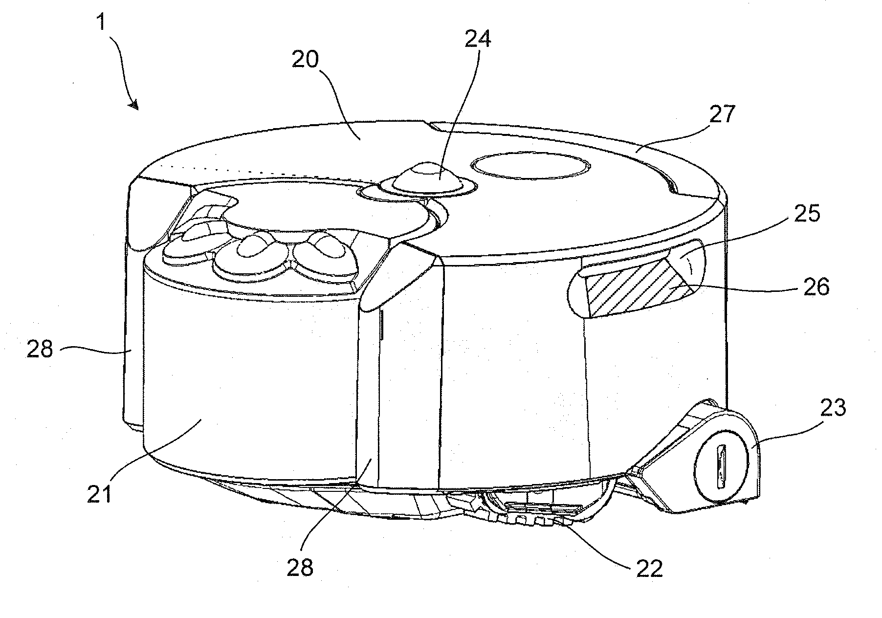
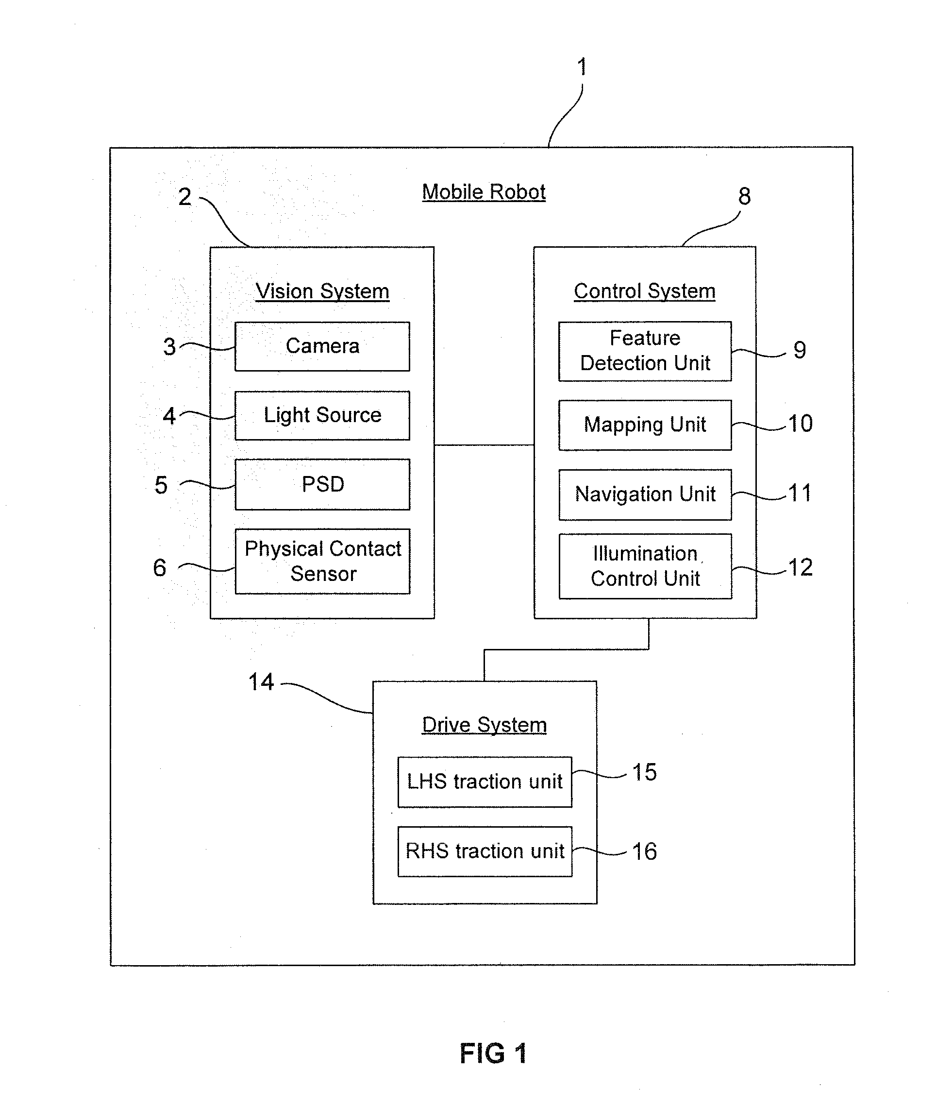
[0031]FIG. 1 shows a schematic illustration of the components of a mobile robot 1. The mobile robot 1 comprises three systems: a vision system 2, a control system 8, and a drive system 14. The combination of these three systems allows the robot 1 to view, interpret and navigate around an environment in which the robot 1 is located. The vision system 2 comprises a camera 3 and a light source 4. The camera 3 is capable of capturing images of an area surrounding the mobile robot 1. For example, the camera 3 may be an upwardly directed camera to capture images of the ceiling, a forward-facing camera to capture images in a forward travelling direction of the robot 1, or may be a panoramic annular lens (PAL) camera that captures a 360° view of the area surrounding the robot 1. The light source 4 is able to improve the quality of the images captured by the camera 3 when the robot 1 is located in an environment that has low-light conditions, or where the images captured by the camera 3 suff...


PUM


Abstract

A mobile robot comprising: a vision system, the vision system comprising a camera and two or more light sources each arranged to provide a level of illumination to an area surrounding the mobile robot; wherein the two or more light sources are arranged to illuminate separate areas surrounding the robot corresponding to different sections of an image captured by the camera, and the level of illumination provided by each of the light sources is independently adjustable.

Description

REFERENCE TO RELATED APPLICATIONS[0001]This application claims priority of United Kingdom Application No. 1415605.3, filed on Sep. 3, 2014, the entire contents of which are incorporated herein by reference.FIELD OF THE INVENTION[0002]The present invention relates to a mobile robot and in particular to a mobile robot capable of illuminating its surroundings.BACKGROUND OF THE INVENTION[0003]Mobile robots are becoming increasingly commonplace and are used in such diverse fields as space exploration, lawn mowing and floor cleaning. Recently there has been a rapid advancement in the field of robotic floor cleaning devices, especially vacuum cleaners, the primary objective of which is to navigate a user's home autonomously and unobtrusively whilst cleaning the floor.[0004]In performing this task, a robotic vacuum cleaner has to navigate the area which it is required to clean. Some robots are provided with a rudimentary navigation system whereby the robot uses what is sometimes referred to...

Claims


Application Information

Patent Timeline
IPC IPC(8): B60Q1/24B60R1/00H04N5/225H04N7/18
CPCB60Q1/24Y10S901/01H04N7/181H04N5/2256G05D1/0231B60R2300/30B60R2300/101B60R1/00B60R2300/80Y10S901/47G05D1/0246G05D2201/0203A47L2201/00B25J11/0085B25J9/0003B25J19/023A47L9/2852A47L2201/04H04N23/56
Inventor JI, ZESMITH, CHRISTOPHER, ANDREW
Owner DYSON TECH LTD
Why Eureka
Try Eureka