

Rotor blade coupling device of a rotor head for a rotary-wing aircraft
- Summary
- Abstract
- Description
- Claims
- Application Information
AI Technical Summary
Benefits of technology
Problems solved by technology
Method used
Image

Examples
Embodiment Construction
[0009]The object of the present invention is to overcome the disadvantages of the rotor blade coupling devices known from prior art, in particular to achieve a simplified structural design of a rotor blade coupling device, wherein the rotor blade coupling device is to enable agile control.
[0010]These objects are achieved by a rotor blade coupling device with the features in patent claim 1.
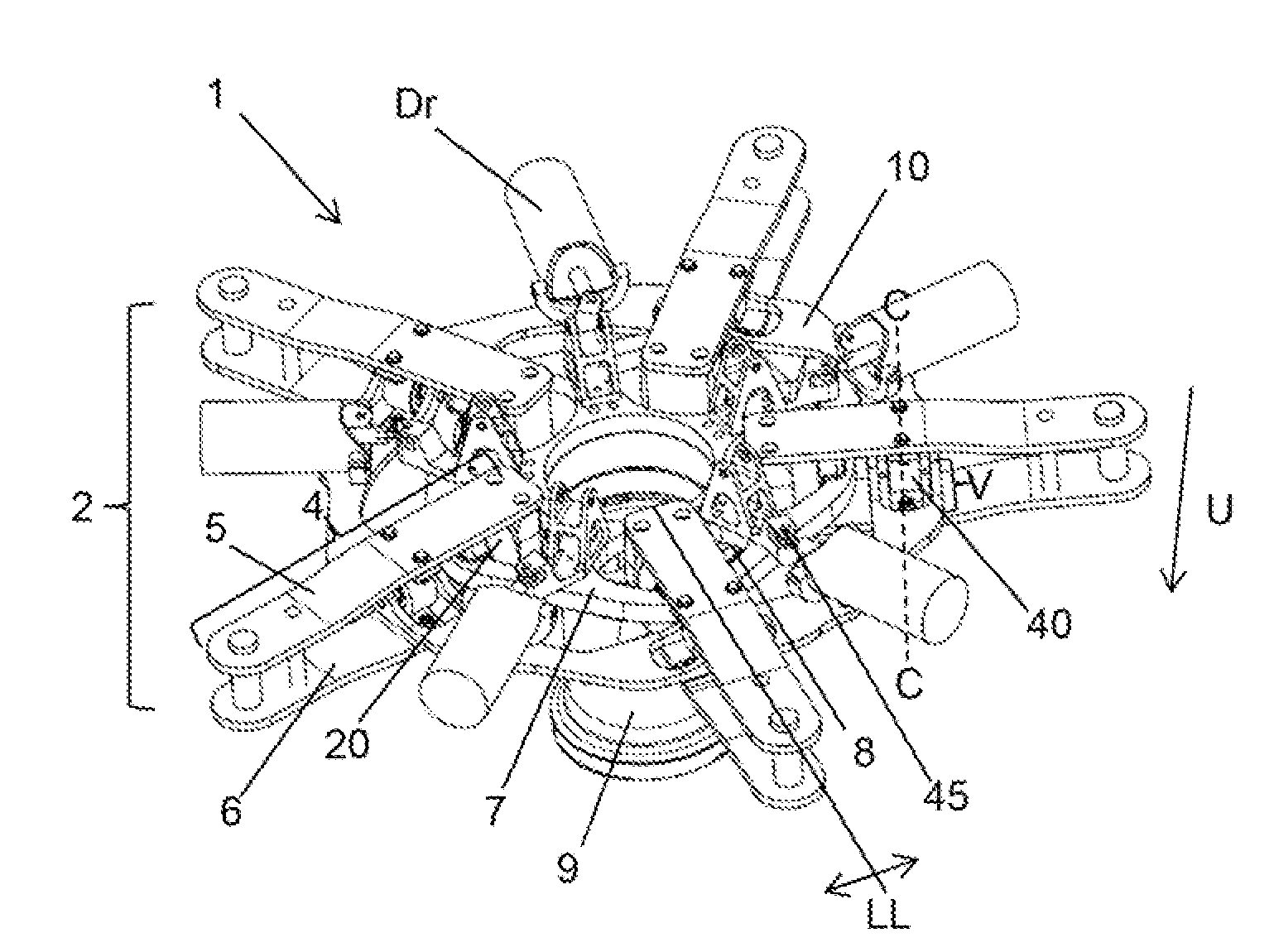
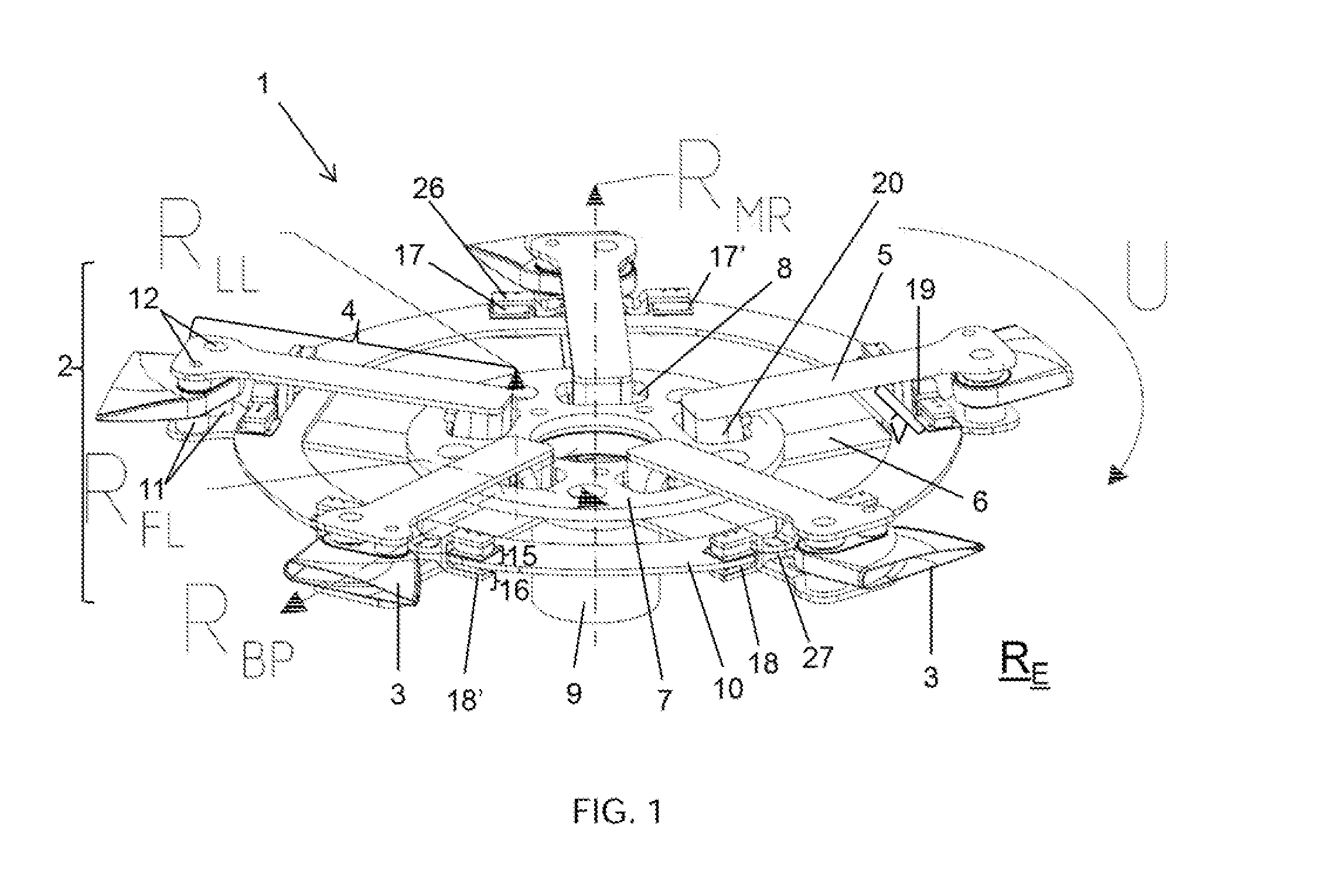
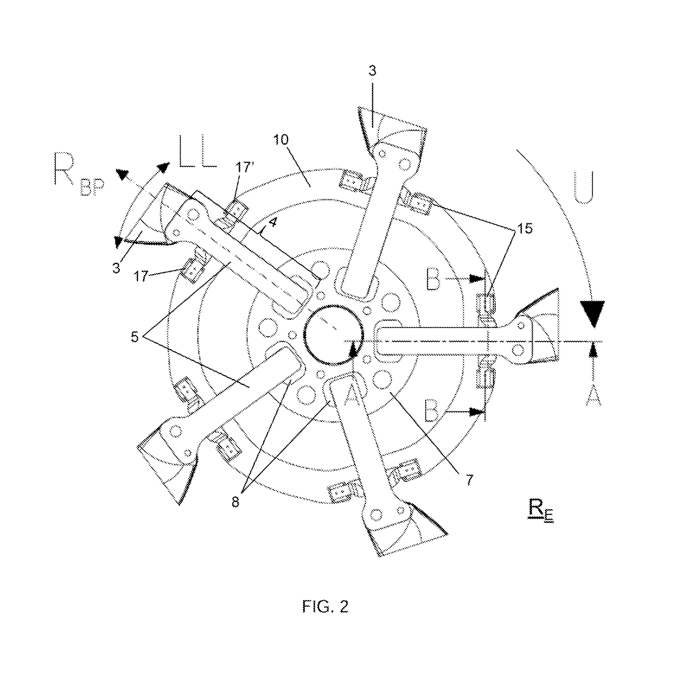
[0011]The rotor blade coupling device according to the invention for coupling with a rotor mast so as to create a rotor head of a rotary-wing aircraft encompasses a rotor head central piece and at least two rotor blade holders fastened thereto for accommodating and fixing at least two rotor blades lying in a rotor plane.
[0012]In addition, at least one joining means is provided between adjacent rotor blade holders.
[0013]According to the invention, the rotor blade coupling device as a joining means encompasses at least one closed ring, wherein the ring is arranged so as to cross all rotor blade holde...
PUM
 Abstract
Description
Claims
Application Information