
Air intake chamber for saddled vehicle

a technology for air intake and saddled vehicles, which is applied in the direction of machines/engines, combustion-air/fuel-air treatment, cycle equipment, etc., can solve the problems of insufficient engine output, achieve effective lowering of intake air temperature, facilitate heat dissipation of intake air, and achieve high heat dissipation capability

Active Publication Date: 2016-03-03
KAWASAKI MOTORS LTD
View PDF14 Cites 6 Cited by
  • Summary
  • Abstract
  • Description
  • Claims
  • Application Information

AI Technical Summary

Benefits of technology

The present invention relates to a device for cooling the intake air of a combustion engine using the heat of evaporation of fuel injected from an injector. The cooling effect increases the engine output and allows for a closer ignition timing. The fuel injecting port is positioned at a displaced position from the air intake chamber outlet, increasing the distance between them to effectively utilize the heat of evaporation. The distance between the injector and the fuel depositing wall surface in the air intake chamber is reduced, reducing the amount of fuel deposit without being evaporated. The injector is inclined diagonally downwardly and rearwardly, stably supporting it and facilitating heat dissipation. The air intake chamber is made of metallic material with high heat dissipating capability, lowering the intake air temperature. The air intake duct passes laterally of the cylinder block, avoiding interference with the injector and component parts. The air intake chamber is inclined downwardly towards rear, increasing the capacity of the fuel tank. The injector is placed on the upper surface of the air intake chamber, avoiding interference with other components. The injector and the upper end of the air intake chamber are held at the same heightwise position.

Problems solved by technology

It has, however, been found that in an automotive vehicle equipped with the supercharger, it has often been experienced that as a result of elevated temperature of a pressurized intake air having its pressure increased, the engine output becomes insufficient.

Method used


Image

  • Air intake chamber for saddled vehicle
  • Air intake chamber for saddled vehicle
  • Air intake chamber for saddled vehicle

Examples


Embodiment Construction

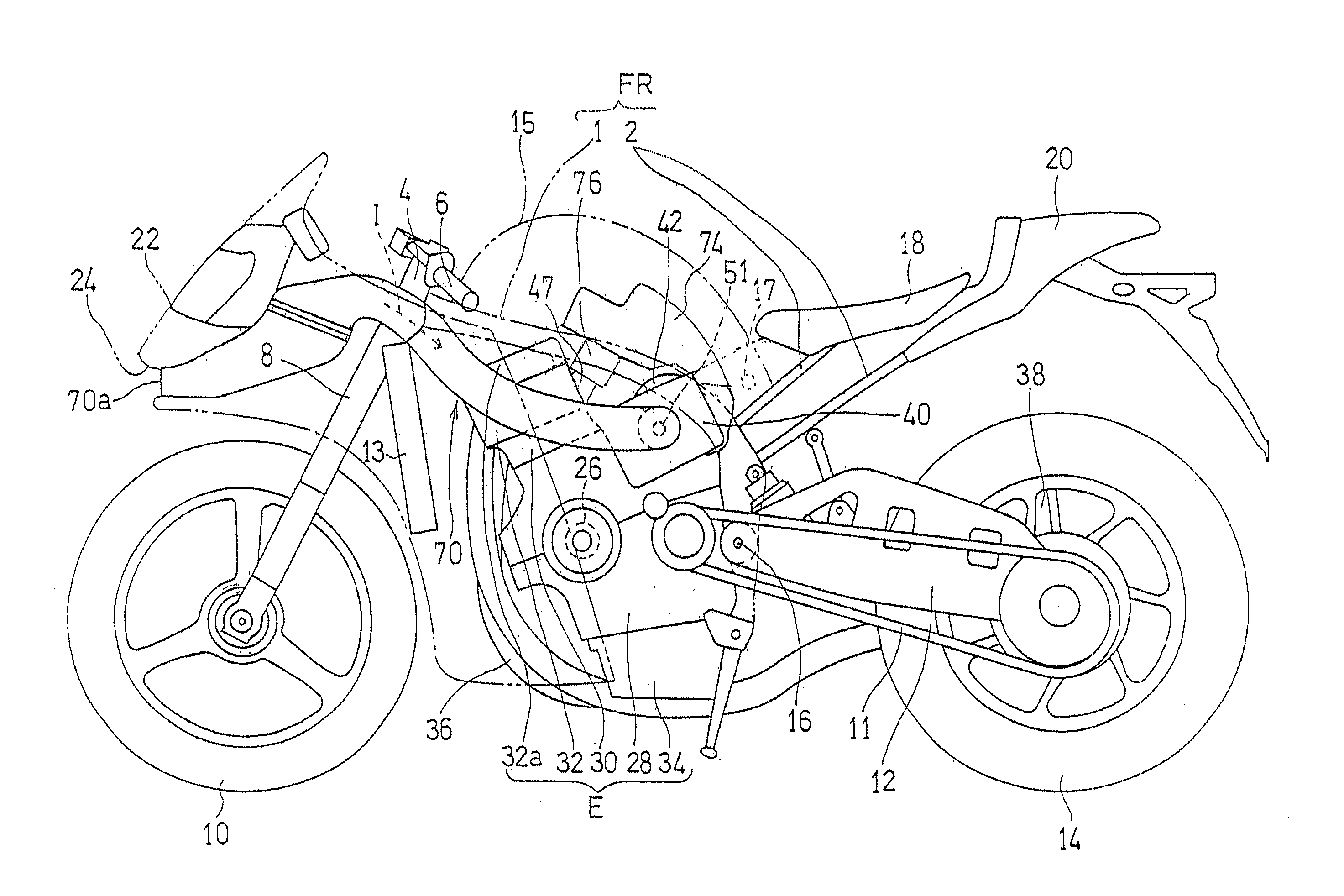
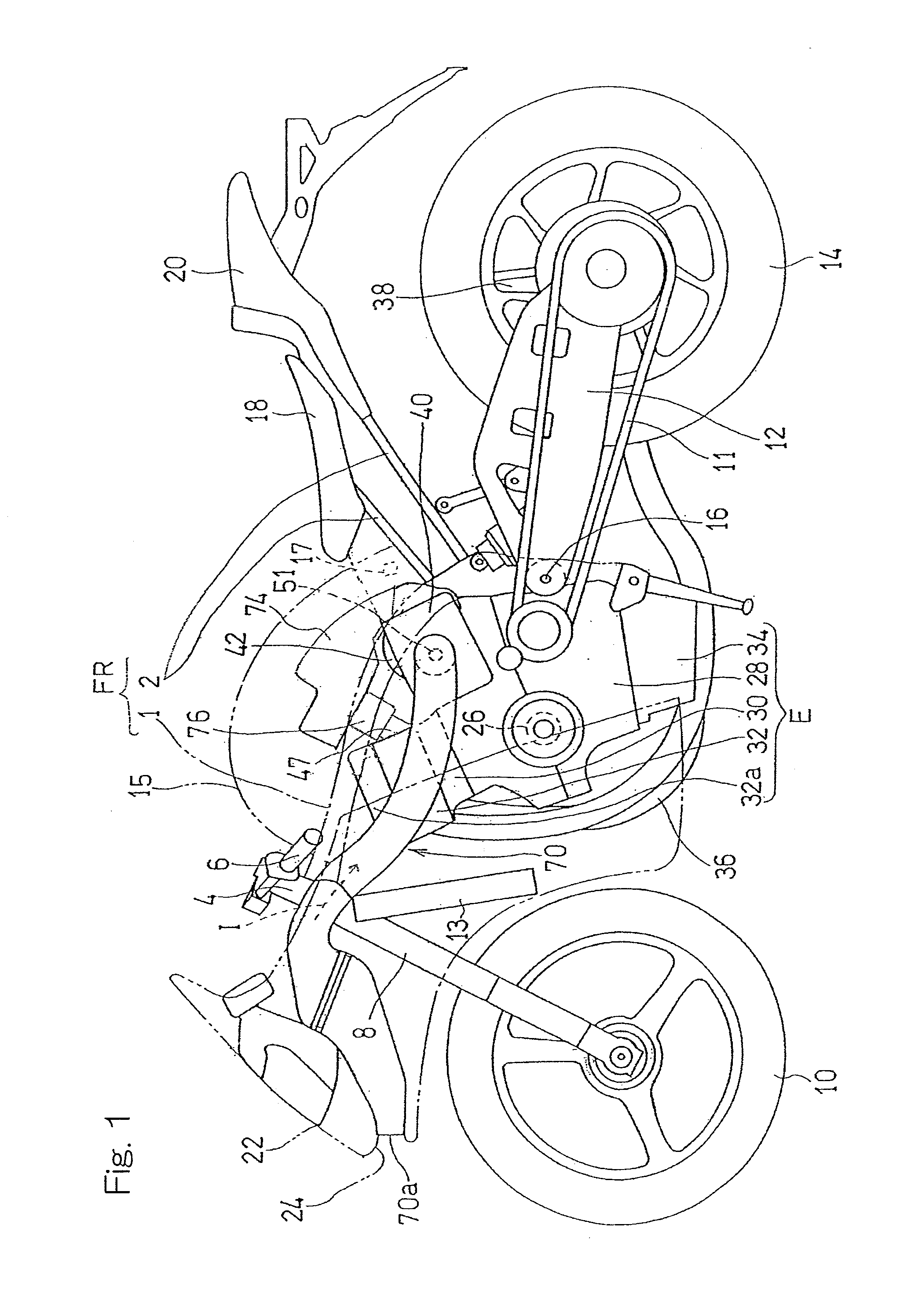
[0028]Hereinafter, a preferred embodiment of the present invention will be described with particular reference to the accompanying drawings. In describing the present invention, however, the terms “left and right” that are used hereinabove and hereinafter are to be understood as relative terms descriptive of positions and / or directions as viewed from a motorcycle rider occupying the seat during the forward travel of the motorcycle.

[0029]FIG. 1 is a left side view of a motorcycle, which is a sort of saddle-riding type vehicle and which is equipped with an air intake chamber designed in accordance with the preferred embodiment of the present invention. The illustrated motorcycle includes a vehicle body frame structure FR, which includes a main frame 1 forming a front half unit thereof and a rear frame 2 fitted to a rear portion of the main frame 1 and forming a rear half unit thereof. A head pipe 4 formed integrally with a front end of the main frame 1 has a front fork 8 rotatably sup...


PUM


Abstract

An air intake chamber for a motorcycle is disposed downstream of a supercharger, for pressurizing and supplying an intake air to an engine, and upstream of a throttle body, for controlling the amount of the intake air to be supplied to an air intake port of the engine. The air intake chamber serves to accumulate the high pressure intake air discharged from the supercharger. The air intake chamber is provided with an injector, which has a fuel injecting port positioned at a location displaced from an axis of an outlet of the air intake chamber.

Description

CROSS REFERENCE TO THE RELATED APPLICATION[0001]This application is a continuation application, under 35 U.S.C §111(a) of international application No. PCT / JP2014 / 051565, filed Jan. 24, 2014, which claims priority to Japanese patent application No. 2013-105486, filed May 17, 2013, the entire disclosure of which is herein incorporated by reference as a part of this application.BACKGROUND OF THE INVENTION[0002]1. Field of the Invention[0003]The present invention relates to an air intake chamber for accumulating an engine intake air that is pressurized by a supercharger.[0004]2. Description of Related Art[0005]Hitherto in a saddle-riding type vehicle equipped with a supercharger, a surge tank is disposed on a downstream side of the supercharger so that air pressurized by the supercharger can be introduced into the surge tank prior to a distributed supply of such pressurized air from the surge tank into a cylinder through the throttle body. In this respect, see, for example, the patent ...

Claims


Application Information

Patent Timeline
Patent Type & Authority Applications(United States)
IPC IPC(8): F02M35/10F02B33/40
CPCF02B33/40F02M35/10216F02M35/10157F02M35/10177F02M35/162B62K19/48F02M35/10091Y02T10/12
Inventor WATANABE, HIROYUKIARIMA, HISATOYOICHI, SATOAKITANAKA, YOSHINOBU
Owner KAWASAKI MOTORS LTD
Features
  • Generate Ideas
  • Intellectual Property
  • Life Sciences
  • Materials
  • Tech Scout
  • Unparalleled Data Quality
  • Higher Quality Content
  • 60% Fewer Hallucinations
Learn More