This helps you quickly interpret patents by identifying the three key elements:
Problems solved by technology
Method used
Benefits of technology
Benefits of technology
The present invention provides an electronic component where the metal layer is less likely to peel off the substrate.
Problems solved by technology
However, an experiment using inverters has found that it is difficult to join the lower electrode obtained by firing the conductor paste to the alumina substrate, and the lower electrode is thus easily peeled from the alumina substrate.
Method used
Image
Click on the blue label to locate the original text in one second.
Reading with bidirectional positioning of images and text.
Examples
first preferred embodiment
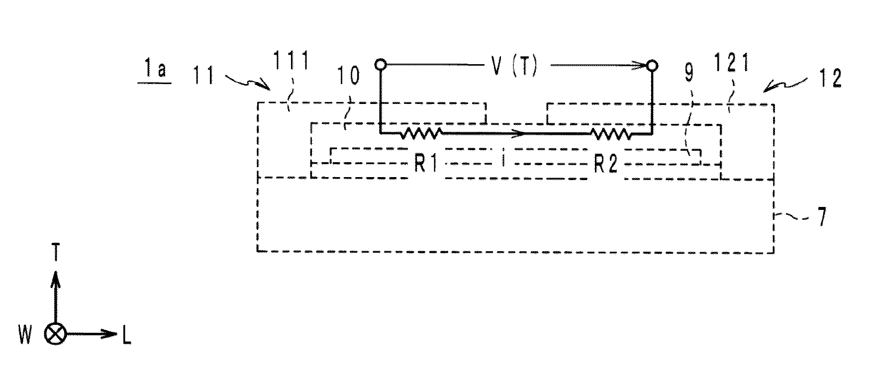
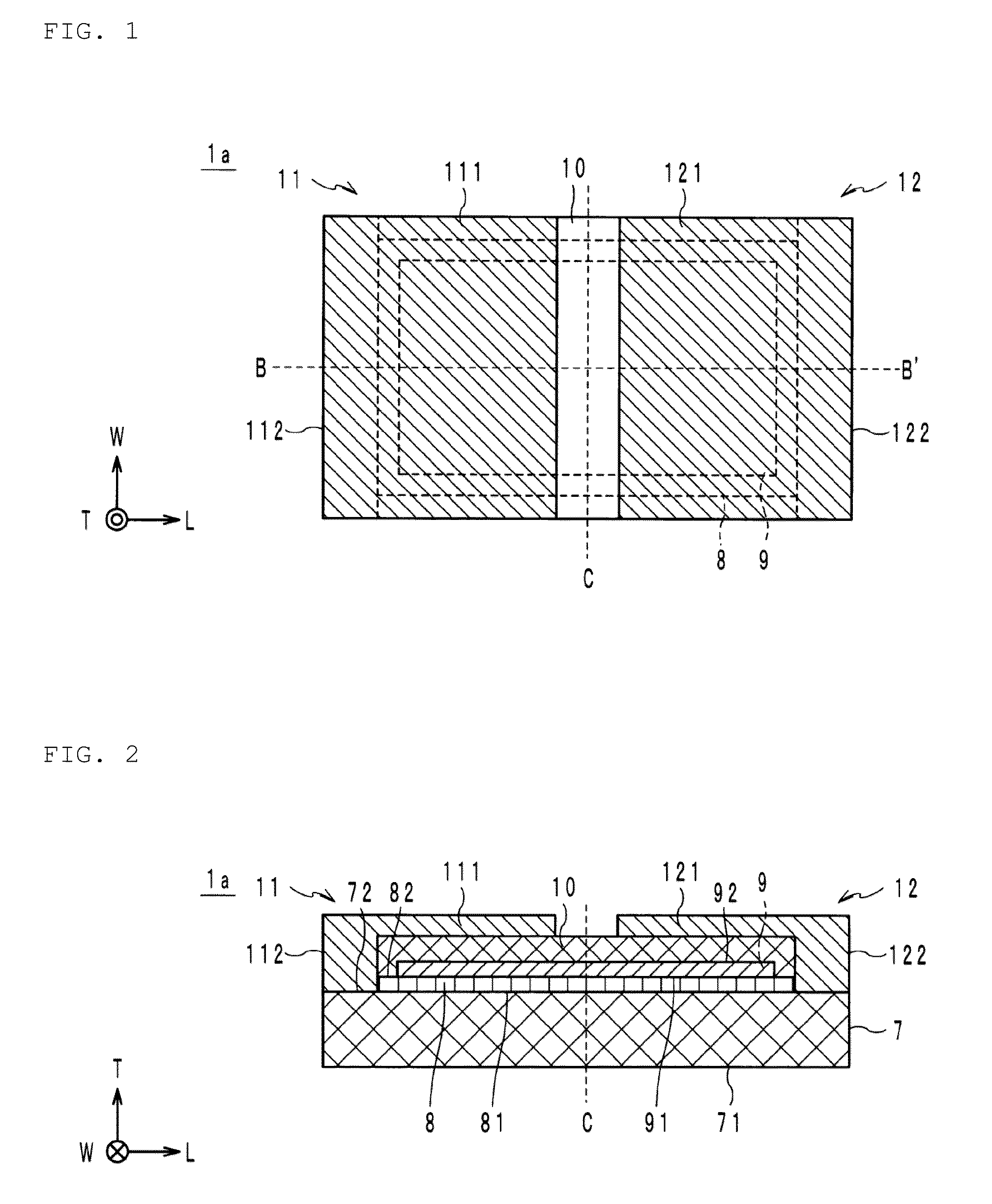
[0017]An electronic component according to a first preferred embodiment of the present invention will be described below. The electronic component according to the first preferred embodiment of the present invention will be described below with reference to the drawings. First, the L axis, W axis, and T axis shown in FIGS. 1 and 2 will be defined. The L axis represents a horizontal direction (length direction) of the electronic component, the W axis represents a front-back direction (depth direction) thereof, and the T axis represents a vertical direction (thickness direction) thereof. The same applies to the other figures regarding the definitions of the L axis, W axis, and T axis.
[0018]As shown in FIGS. 1 and 2, the electronic component la includes a substrate 7, a ceramic layer 8, an internal electrode 9, a thermistor characteristic layer 10, a first external electrode 11, and a second external electrode 12.
[0019]The substrate 7 is preferably made of an insulating ceramic contain...
second preferred embodiment
[0046]As shown in FIGS. 5 and 6, an electronic component lb preferably includes a substrate 2, a first metal layer 3, a second metal layer 4, a thermistor characteristic layer 5, a third metal layer 6, and a ceramic layer 18.
[0047]The substrate 2 is prepared from the similar insulating ceramic to the substrate 7 described above. The substrate 2 includes two principal surfaces 21, 22 mutually opposed in the vertical direction, and preferably has, for example, a rectangular or substantially rectangular shape as viewed from above. In this regard, the principal surface 22 is located in the positive area in the T axis direction with the principal surface 21 as a reference in the present preferred embodiment.
[0048]The first metal layer 3 and the second metal layer 4 are typically prepared from a single noble metal or an alloy of multiple noble metals. In the present preferred embodiment, the layers are prepared from a metal paste containing silver and palladium. In addition, the metal lay...
PUM
Abstract
An electronic component in which a metal layer is unlikely to be peeled from a substrate includes an insulating ceramic substrate, a ceramic layer diffusion-bonded to the substrate, a metal layer including a first principal surface and a second principal surface opposed to the first principal surface, with the first principal surface diffusion-bonded to the ceramic layer, and a characteristic layer diffusion-bonded to the second principal surface of the metal layer and prepared from a ceramic material, wherein the characteristic layer varies in resistance value with respect to ambient temperature or applied voltage.
Description
BACKGROUND OF THE INVENTION[0001]1. Field of the Invention[0002]The present invention relates to an electronic component including a substrate and a ceramic characteristic layer provided on the substrate.[0003]2. Description of the Related Art[0004]Conventionally, as this type of electronic component includes, for example, a thick film thermistor described in Japanese Patent Application Laid-Open No. 7-99101. This thick film thermistor is prepared in accordance with the following steps. More specifically, a conductor paste is applied onto one surface of an alumina substrate as an example of an insulating substrate, and is subjected to firing to form a lower electrode on the alumina substrate. Subsequently, a paste for thick film thermistors is applied so as to have a partial overlap with the lower electrode, and subjected to firing to form a thick film thermistor.[0005]In Japanese Patent Application Laid-Open No. 7-99101, the conductor paste is applied onto the fired alumina substra...
Claims
Application Information
Patent Timeline
Application Date:The date an application was filed.
Publication Date:The date a patent or application was officially published.
First Publication Date:The earliest publication date of a patent with the same application number.
Issue Date:Publication date of the patent grant document.
PCT Entry Date:The Entry date of PCT National Phase.
Estimated Expiry Date:The statutory expiry date of a patent right according to the Patent Law, and it is the longest term of protection that the patent right can achieve without the termination of the patent right due to other reasons(Term extension factor has been taken into account ).
Invalid Date:Actual expiry date is based on effective date or publication date of legal transaction data of invalid patent.

