
Current cut-off device for high-voltage direct current with capacitive buffer circuit, and control method

a capacitive buffer circuit and current cut-off device technology, applied in the direction of high-tension/heavy-dress switch, electrical apparatus, and electrical devices responsive to excess voltage, can solve the problems of complex calibration of oscillation current, high price/power ratio of components, and increase the cost of solutions

Pending Publication Date: 2022-01-27
SUPERGRID INSTITUTE SAS
View PDF4 Cites 0 Cited by
  • Summary
  • Abstract
  • Description
  • Claims
  • Application Information

AI Technical Summary

Benefits of technology

The invention proposes a current cut-off device for high-voltage DC electrical current that includes a primary switch and a secondary switch arranged in a line between a primary point and a secondary point. The device also includes a capacitive buffer circuit with an activation switch and a buffer capacitance arranged in parallel with the primary and secondary switches. The device also includes a primary surge protector and a secondary surge protector arranged between the intermediate point and the secondary point. The device can be controlled using a method that involves mechanically opening and closing the switches and using the activation switch to allow a current to flow through the device while charging the buffer capacitance. The device can also include a damping resistor and a bypass switch for discharging the buffer capacitance. The technical effects of the invention include improved current cut-off capabilities, reduced surge protector size, and improved control methods.

Problems solved by technology

However, these components have a high price / power ratio.
Excessive use of such semiconductor switches increases the cost of the solution.
It is however noted that the calibration of the oscillation current is complex because it must ensure a zero crossing under conditions that must simultaneously allow the extinction of the arc in the two switches.
If this is possible for predetermined values of fault current intensity, it becomes very complex to obtain the desired result for disparate values of fault current intensity.
Since this solution is based on the voltage of the switch arc to create a zero crossing of the current in the first switch 42, it is very difficult to interrupt a high fault current.
With this solution, it is difficult to interrupt a high-intensity current.
In summary, according to the prior art, there is no solution having a current interrupting capability greater than 10 kiloamperes (kA) with reasonable size and cost.

Method used


Image

  • Current cut-off device for high-voltage direct current with capacitive buffer circuit, and control method
  • Current cut-off device for high-voltage direct current with capacitive buffer circuit, and control method
  • Current cut-off device for high-voltage direct current with capacitive buffer circuit, and control method

Examples


Embodiment Construction

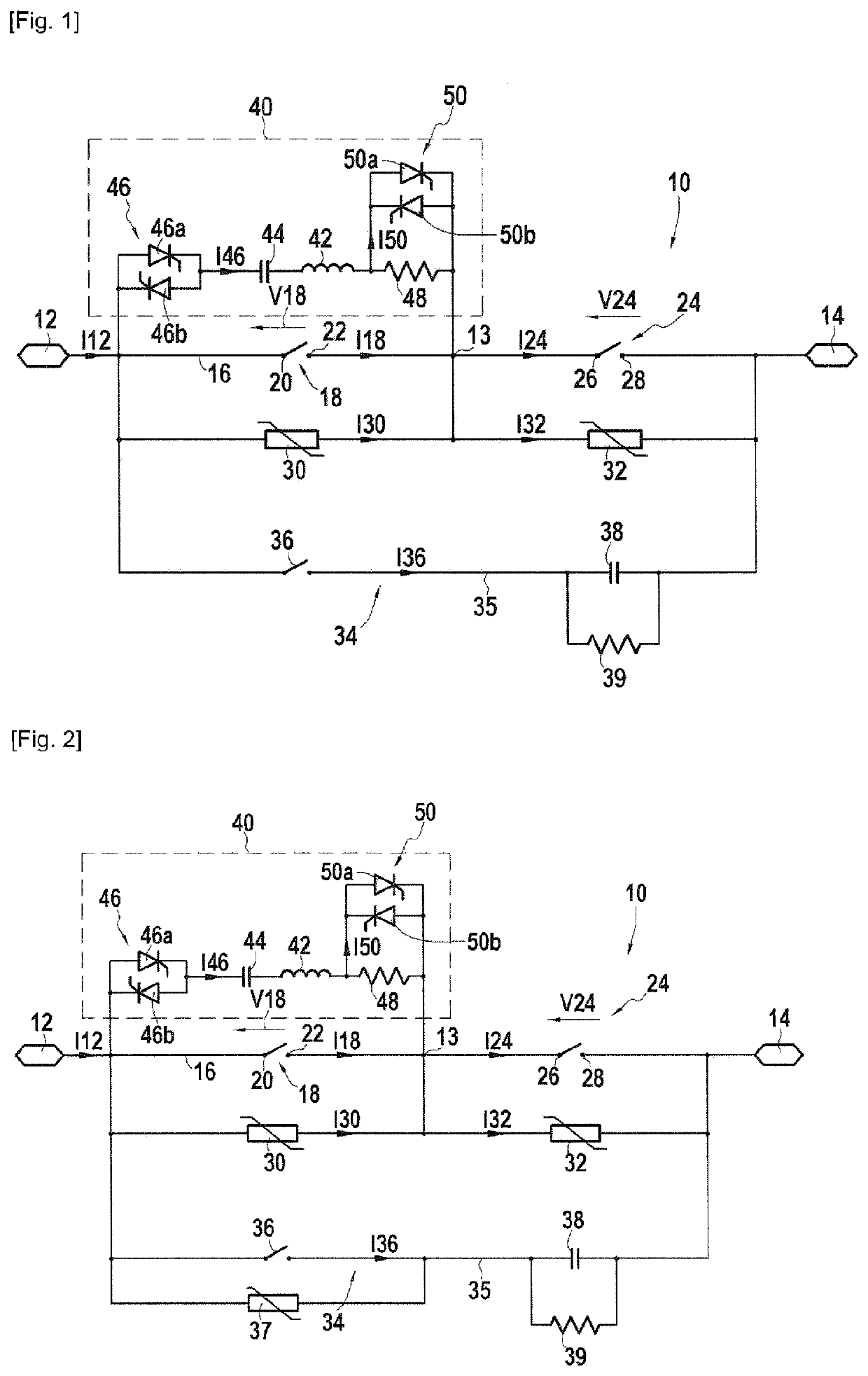
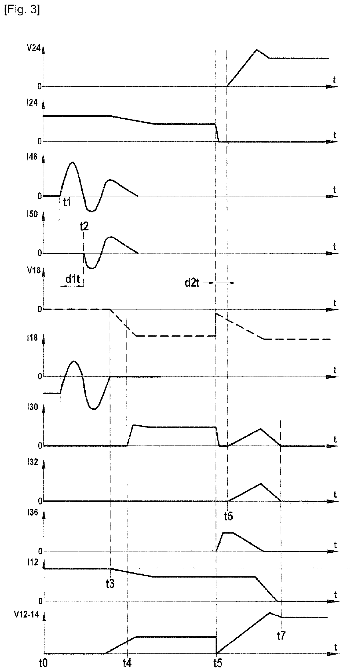
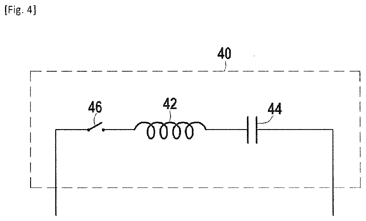
[0050]FIG. 1 is a schematic representation of a first embodiment of a cut-off apparatus 10 according to the invention, for high-voltage, even very high-voltage, DC current.

[0051]As can be seen in FIG. 1, the current cut-off device 10 includes a primary point, which may be a first terminal 12, and a secondary point, which may be a second terminal 14. This primary point 12 and this secondary point 14, or terminals, form inputs / outputs for the current in the device 10. Each of these points may correspond to a physical terminal of the device 10, for example a physical connection terminal, or a virtual terminal of the device 10 as being a point along a conductor.

[0052]The device 10 includes a main line 16 which extends between the first terminal 12 and the second terminal 14 and in which are interposed, successively in the main line between the primary point 12 and the secondary point 14, a primary switch 18, having a first terminal 20 and a second terminal 22, and a secondary switch 24,...


PUM

PropertyMeasurementUnit
voltageaaaaaaaaaa
operating voltageaaaaaaaaaa
voltageaaaaaaaaaa

Abstract

A high-voltage direct current cut-off device, includes: a primary mechanical switch and a secondary mechanical switch placed successively between a primary point and a secondary point but either side of an intermediate point, a primary surge arrester arranged parallel with the primary switch, a secondary surge arrester arranged electrically parallel with the secondary switch. The secondary surge arrester is arranged electrically between the intermediate point and the secondary point, and in that the device comprises a capacitive buffer circuit electrically in parallel with the assembly formed by the primary switch and the secondary switch, and electrically in parallel with the assembly formed by the primary surge arrester and the secondary surge arrester, wherein the capacitive buffer circuit comprises an activation switch and a buffer capacitance.

Description

TECHNICAL FIELD[0001]The invention relates to the field of high-voltage DC electrical current transmission and / or distribution networks, generally referred to as HVDC networks. The invention particularly relates to fault current cut-off devices intended for such networks.[0002]HVDC networks are in particular envisaged as a solution to the interconnection of disparate or non-synchronous electricity production sites. HVDC networks are in particular envisaged for the transmission and the distribution of energy produced by offshore wind farms rather than alternating current technologies, due to lower line losses and to the absence of impact of the parasitic capacitances of the network on long distances. Such networks typically have voltage levels on the order of 100 kV and more.[0003]In the present text, a device in which the nominal operating voltage is greater than 1,500 V in direct current is considered as a high voltage, for a direct current. Such a high voltage is, in a complementa...

Claims


Application Information

Patent Timeline
Patent Type & Authority Applications(United States)
IPC IPC(8): H02H3/20H02H9/04H02H9/00
CPCH02H3/202H02H9/005H02H9/04H01H33/596H01H2009/543H01H2009/544
Inventor YANG, YANG
Owner SUPERGRID INSTITUTE SAS
Learn More