
Power amplifier circuit

a power amplifier and circuit technology, applied in the direction of rf amplifiers, high frequency amplifiers, gain control, etc., can solve the problem of difficulty in adjusting the gain dispersion rang

Active Publication Date: 2020-04-16
MURATA MFG CO LTD
View PDF0 Cites 1 Cited by
  • Summary
  • Abstract
  • Description
  • Claims
  • Application Information

AI Technical Summary

Benefits of technology

The patent is about a power amplifier circuit that can adjust the range of gain dispersion. This means that the circuit can control the variation in how well the amplified signal is received. This makes it easier to design and test the circuit, and ensures consistent performance.

Problems solved by technology

However, in the bias circuit disclosed in Japanese Unexamined Patent Application Publication No. 2014-171170, it is difficult to adjust the range of gain dispersion.

Method used


Image

  • Power amplifier circuit
  • Power amplifier circuit
  • Power amplifier circuit

Examples


Embodiment Construction

[0045]An embodiment of the present disclosure will be described below with reference to the drawings. Here, circuit elements denoted by the same reference numerals are identical, and a repeated description thereof is omitted.

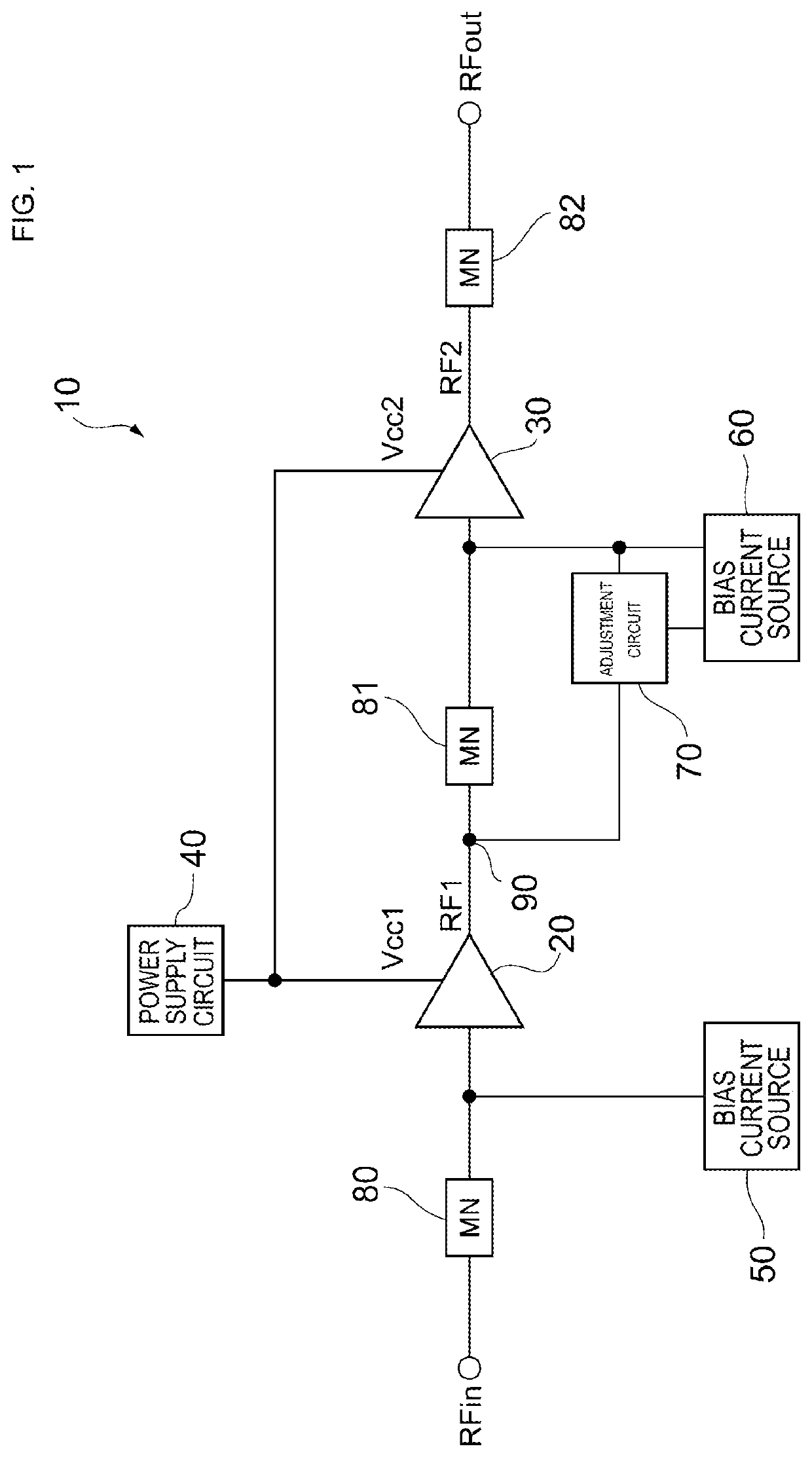
[0046]FIG. 1 illustrates an overview of a configuration of a power amplifier module including a power amplifier circuit according to an embodiment of the present disclosure. A power amplifier module 10 is installed, for example, in a mobile communication device, such as a cellular phone. The power amplifier module 10 amplifies the power of an input signal RFin to a level necessary to transmit the input signal RFin to a base station and outputs this input signal RFin as an amplified signal RFout. The input signal RFin is a radio frequency (RF) signal modulated, for example, by a radio frequency integrated circuit (RFIC) or the like in accordance with a certain communication scheme. Examples of a communication standard of the input signal RFin include the second g...


PUM


Abstract

A power amplifier circuit includes a first transistor that amplifies an RF signal; a bias current source that supplies a bias current to a second terminal of the first transistor through a first current path; and an adjustment circuit that adjusts the bias current in accordance with a variable power-supply voltage supplied from a power-supply terminal. The adjustment circuit includes first to third resistors, and an adjustment transistor including a first terminal connected to the power-supply terminal through the first resistor, a second terminal connected to the bias current source through the second resistor, and a third terminal connected to the first current path through the third resistor. When the variable power-supply voltage is not less than a first voltage and not greater than a third voltage, the adjustment circuit increases a current that flows to the power-supply terminal through a second current path as the variable power-supply voltage decreases.

Description

[0001]This application claims priority from Japanese Patent Application No. 2018-193611, filed on Oct. 12, 2018, and claims priority from Japanese Patent Application No. 2019-113497, filed on Jun. 19, 2019. The contents of these applications are incorporated herein by reference in their entireties.BACKGROUND OF THE DISCLOSURE1. Field of the Disclosure[0002]The present disclosure relates to a power amplifier circuit.2. Description of the Related Art[0003]In mobile communication terminals, such as cellular phones, a power amplifier circuit is used that amplifies a radio frequency (RF) signal to be transmitted to a base station. The power amplifier circuit includes a transistor that amplifies the RF signal, and a bias circuit that controls a bias point of the transistor. For example, as disclosed in Japanese Unexamined Patent Application Publication No. 2014-171170, there is a power amplifier circuit including, as this type of bias circuit, an emitter follower transistor configured to ...

Claims


Application Information

Patent Timeline
Patent Type & Authority Applications(United States)
IPC IPC(8): H03F1/02H03F3/21H03F1/56H03G1/00H03G3/30
CPCH03F2200/387H03F3/21H03F2200/222H03G3/3036H03G1/0017H03F2200/318H03F2200/451H03F1/56H03G2201/307H03F1/0211H03G1/0082H03F2200/102H03F3/245H03F3/19H03F1/3241H03F1/565H03F3/191H03F1/22H03F2200/363H03G3/3042H03G1/0088
Inventor SHIMAMOTO, KENICHINAMIE, HISANORI
Owner MURATA MFG CO LTD
Learn More