
Surface analysis and measurement method based on flow resistance of fluid and atomic force microscope using the method

a flow resistance and flow analysis technology, applied in the direction of instruments, using fluid means, coatings, etc., can solve the problems of difficult or impossible to measure steeply inclined surface portions like narrow and deep valleys, too low vertical resolution to observe individual atoms, etc., to achieve the effect of improving accuracy and rapid acquisition, and being easy to observe and simple to us

Inactive Publication Date: 2012-11-27
KOREA ADVANCED INST OF SCI & TECH
View PDF9 Cites 0 Cited by
  • Summary
  • Abstract
  • Description
  • Claims
  • Application Information

AI Technical Summary

Benefits of technology

"The present invention provides a method for analyzing and measuring the surface of a sample based on the flow resistance of a fluid sprayed on the sample. This method is simple and accurate compared to conventional mechanical probing methods. It also provides an atomic force microscope that can measure the surface topography of a sample by injecting and sucking a functional liquid. The microscope can measure the surface topography of a sample by calculating the variation in flow resistance of the fluid caused by the movement of the sample. The method and microscope can provide information about the surface topography and flatness of a sample with high accuracy and without any convolution effect caused by the shape of the probe. The method and microscope can also be used in chemical and biological engineering fields for injection and suction of functional liquids."

Problems solved by technology

Transmission electron microscopes (TEMs) have a horizontal resolution on the atomic scale, but they have too low a vertical resolution to observe individual atoms.
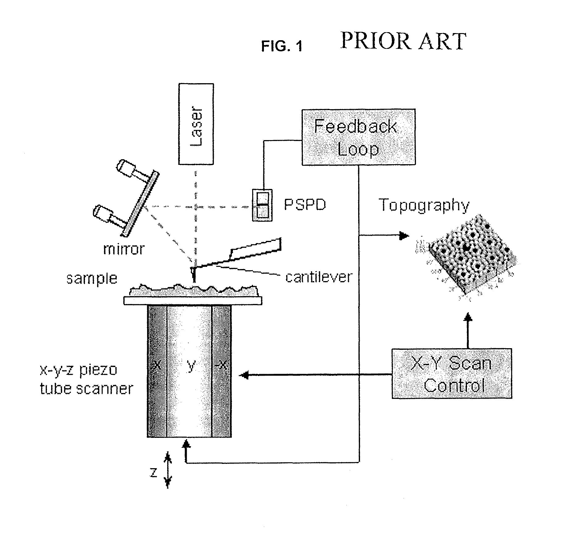
However, a problem of the prior art atomic force microscope is that the probe mechanically moves along the sample surface, which renders the imaging speed slower than that of an optical microscope or an electron microscope.
Further, a flexible size of the probe makes it difficult or impossible to measure steeply inclined surface portions like narrow and deep valleys.
Moreover, convolution effect due to the shape of the probe causes measurement errors even in measurable portions of the sample.
Furthermore, the atomic force microscope suffers from poor accuracy of operation.

Method used


Image

  • Surface analysis and measurement method based on flow resistance of fluid and atomic force microscope using the method
  • Surface analysis and measurement method based on flow resistance of fluid and atomic force microscope using the method
  • Surface analysis and measurement method based on flow resistance of fluid and atomic force microscope using the method

Examples


first embodiment

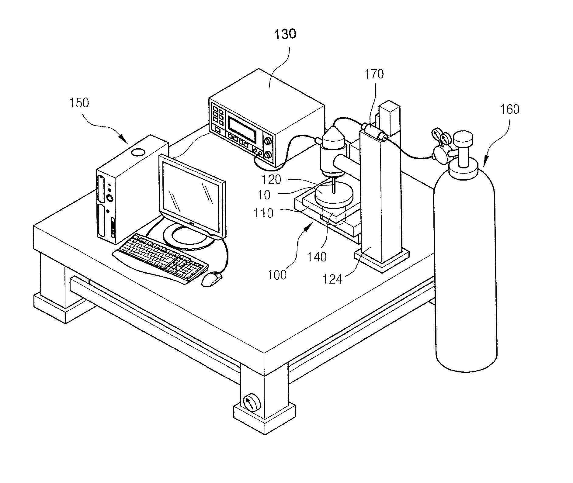
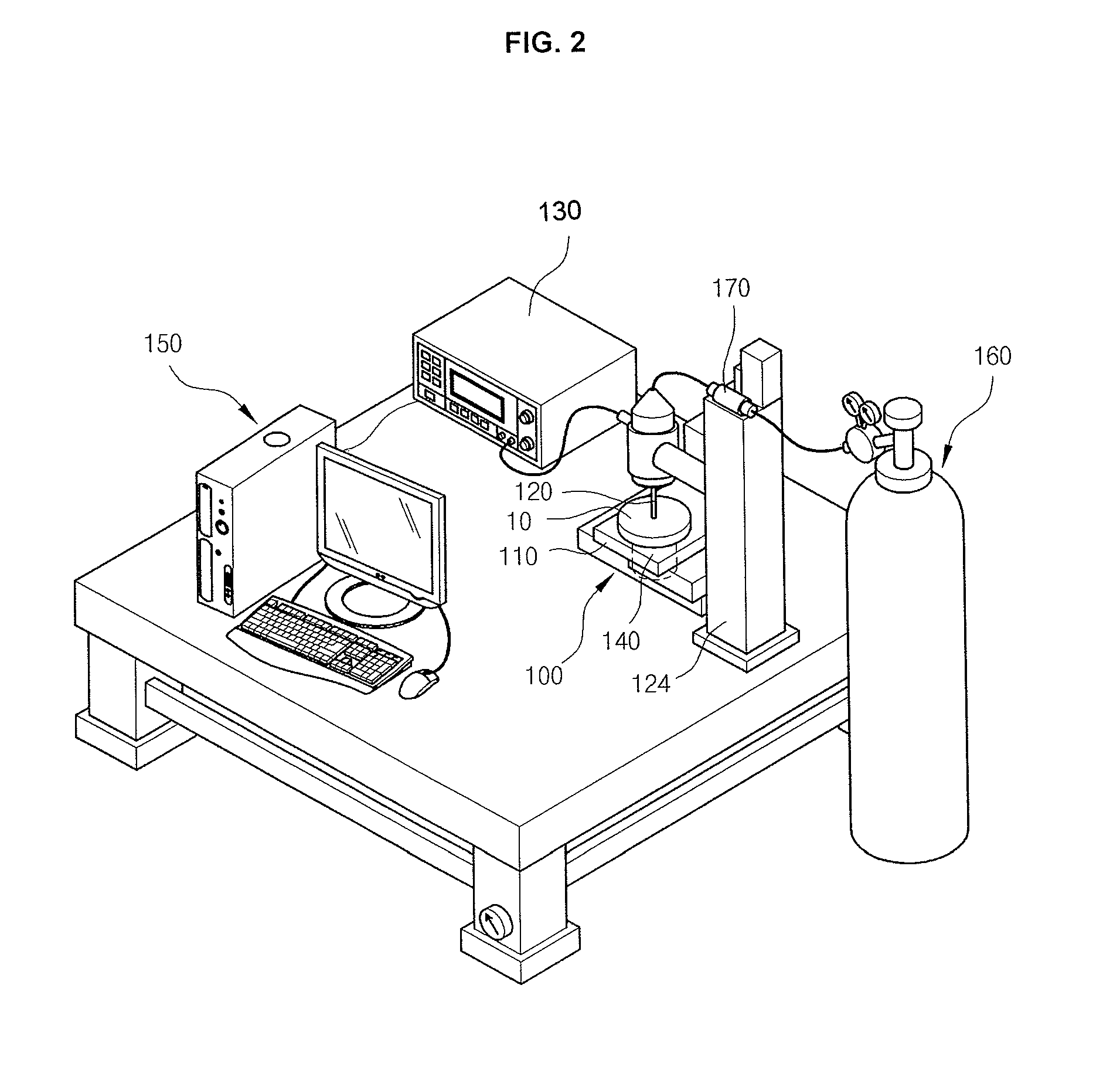
[0094] shown in FIG. 7b, the nozzle 120 further includes a connecting tube 123 branched from the outer circumference of the connecting part 121 to supply a functional liquid to the connecting part 121 therethrough. The functional liquid joins the fluid supplied through the flow valve 170 and is sprayed in a limited range on a particular location of the sample surface through the hole of the nozzle tip 122.

[0095]For example, the functional liquid may be a coating liquid or a liquid chemically reacting with the sample 10. The fluid provided to measure the surface of the sample 10 joins the functional liquid in the nozzle 120. The pressure of the fluid allows the functional liquid to be sprayed on a particular portion of the sample surface in a limited range. Therefore, the functional liquid can be accurately sprayed on a particular location of the sample 10 having a fine topography on a nanometer scale. This embodiment can further extend the applicability of the atomic force microscop...

second embodiment

[0096] shown in FIG. 7c, the atomic force microscope 100 further comprises a pump180 for creating a vacuum in the connecting tube 123 in a state in which the functional fluid and the liquid are not sprayed through the nozzle 120, to extract a target molecule present at a particular location of the sample 10 through the hole 122a of the nozzle tip 122 by a suction force.

[0097]This embodiment can be applied to microbiological fields, such as cloning, which is being developed at present.

[0098]Treatment of biological cells is important in microbiology.

[0099]Injection of particular DNA into cell nuclei is gaining more importance. It takes a long time for a researcher to acquire a manual technique for injecting biological cells. Further, the results are greatly affected by the skill of the researcher.

[0100]Furthermore, the manual injection increases the possibility of cell contamination, resulting in low reproducibility. Thus, there is a need for a mechanical method that can increase the ...


PUM


Abstract

Provided is a surface analysis and measurement method based on the flow resistance of a fluid. The method comprises: spraying a fluid on the surface of a sample; identifying and determining if a flow resistance value of the fluid colliding with the sample surface is optimal for the measurement of the surface topography of the sample; setting the determined optimal flow resistance value to a reference value and moving the sample in the X-Y axes to allow the entire surface of the sample to be scanned; varying the position of the sample in the Z axis together with the X-Y axis movement to adjust varying flow resistance values of the fluid along the irregular surface topography of the sample to the set flow resistance value during scanning; and expressing the movement ranges of the sample in the X, Y and Z axes as numerical values and representing the numerical values as brightness values on a computer screen to display the surface topography of the sample. Further provided is an atomic force microscope using the method.

Description

BACKGROUND OF THE INVENTION[0001]1. Field of the Invention[0002]The present invention relates to a surface analysis and measurement method based on the flow resistance of a fluid, and an atomic force microscope using the method. More specifically, the present invention relates to a method for precisely analyzing and measuring the surface of a nanometer-sized sample by utilizing flow resistance resulting from a flow of a fluid, and an atomic force microscope using the method.[0003]2. Description of the Related Art[0004]SPM is an abbreviation for scanning probe microscope and is a generic term for a new concept of microscope capable of measuring the surface characteristics of materials at the atomic level. In Korea, SPM is simply called an atomic microscope. SPM has overcome the generally accepted truth that atoms are too small (0.1-0.5 nm) to be seen even with the aid of very advanced microscopes. Optical microscopes, scanning electron microscopes (SEMs) and scanning probe microscope...

Claims


Application Information

Patent Timeline
Patent Type & Authority Patents(United States)
IPC IPC(8): G01B13/16
CPCB82Y15/00G01Q30/04G01Q30/14G01Q60/38B82Y35/00G01Q60/24G01B13/00G02B21/00
Inventor KIM, SUNG JINKIM, TAE YOUNGKIM, DONG KWON
Owner KOREA ADVANCED INST OF SCI & TECH
Learn More