

Lighting apparatus and luminaire
a technology of light-emitting devices and luminaires, which is applied in the direction of electroluminescent light sources, electric lighting sources, and use of semi-conductor lamps, can solve the problems of increasing noise filter costs, increasing switching losses, and reducing circuit efficiency, and achieves the effect of suppressing the variation in the switching frequency of dc/dc converters
- Summary
- Abstract
- Description
- Claims
- Application Information
AI Technical Summary
Benefits of technology
Problems solved by technology
Method used
Image

Examples
embodiment 1
[1-1. Configuration of Entire Lighting Apparatus]
[0030]First, configuration of an entire lighting apparatus according to Embodiment 1 will be described.
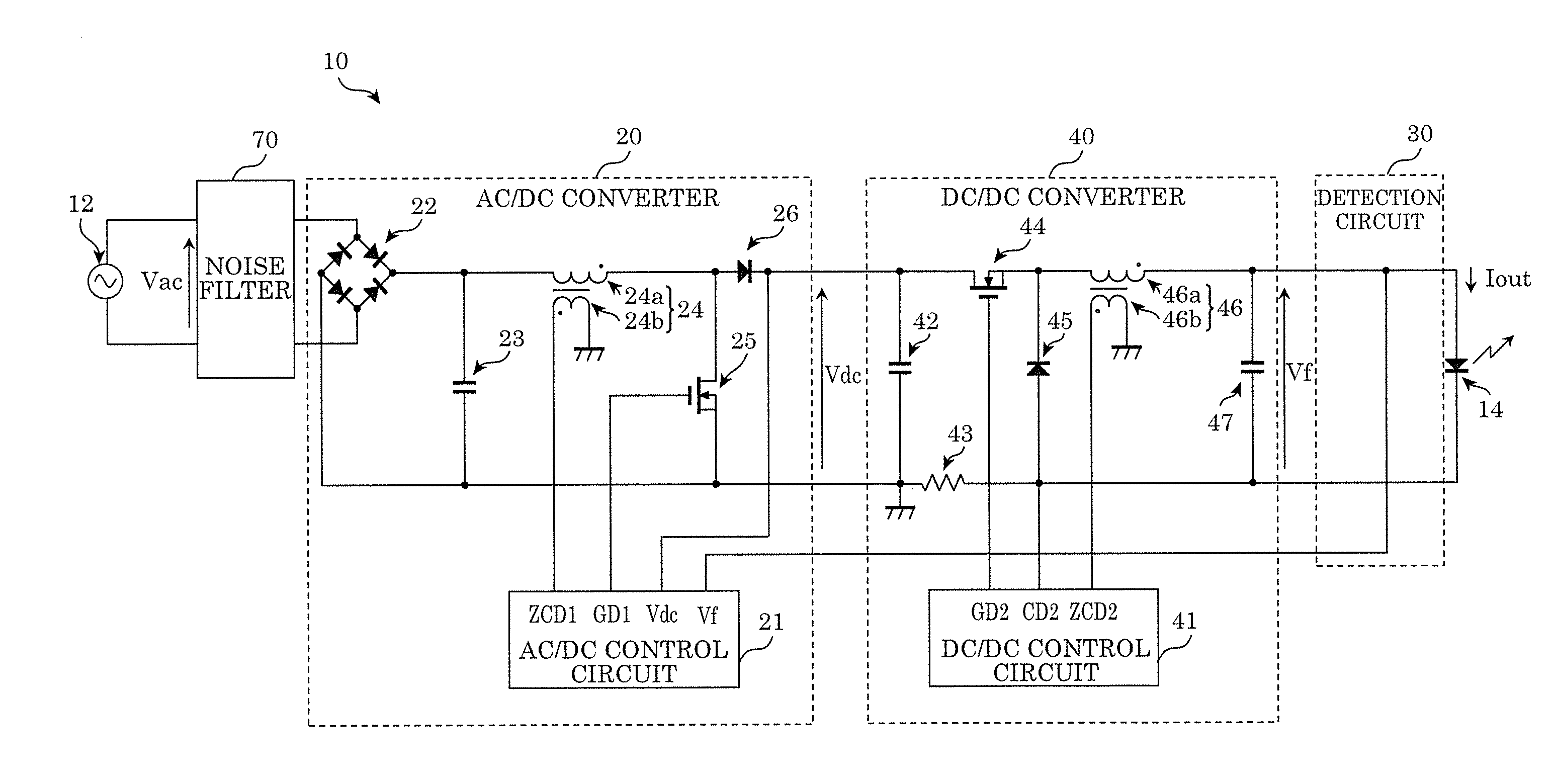
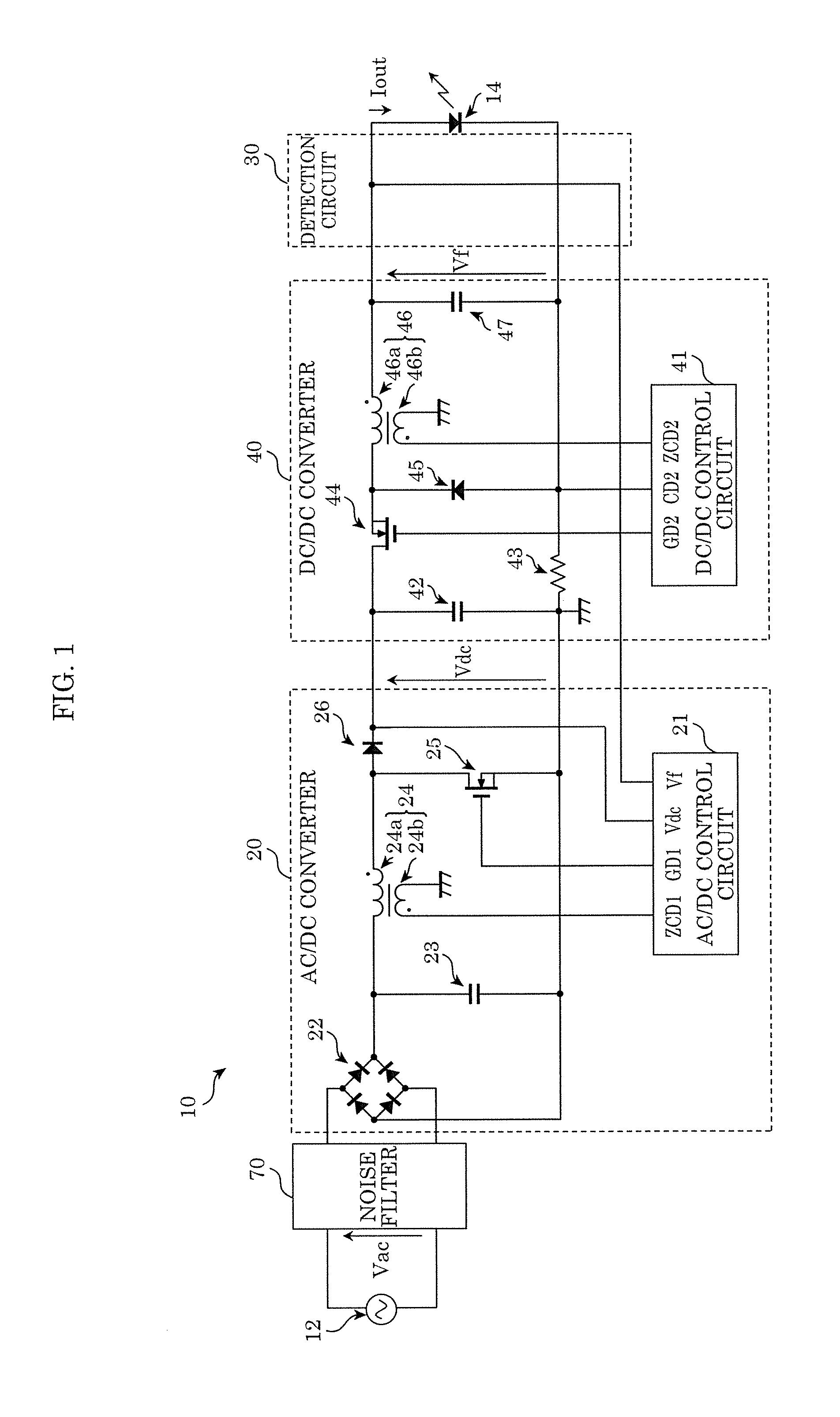
[0031]FIG. 1 is a circuit diagram illustrating a circuit configuration of lighting apparatus 10 according to Embodiment 1. FIG. 1 also illustrates AC power supply 12 (a commercial power supply, for example) which generates an AC voltage provided to lighting apparatus 10, and LED 14 which is an example of a solid-state light-emitting device to which a current output from lighting apparatus 10 is supplied.
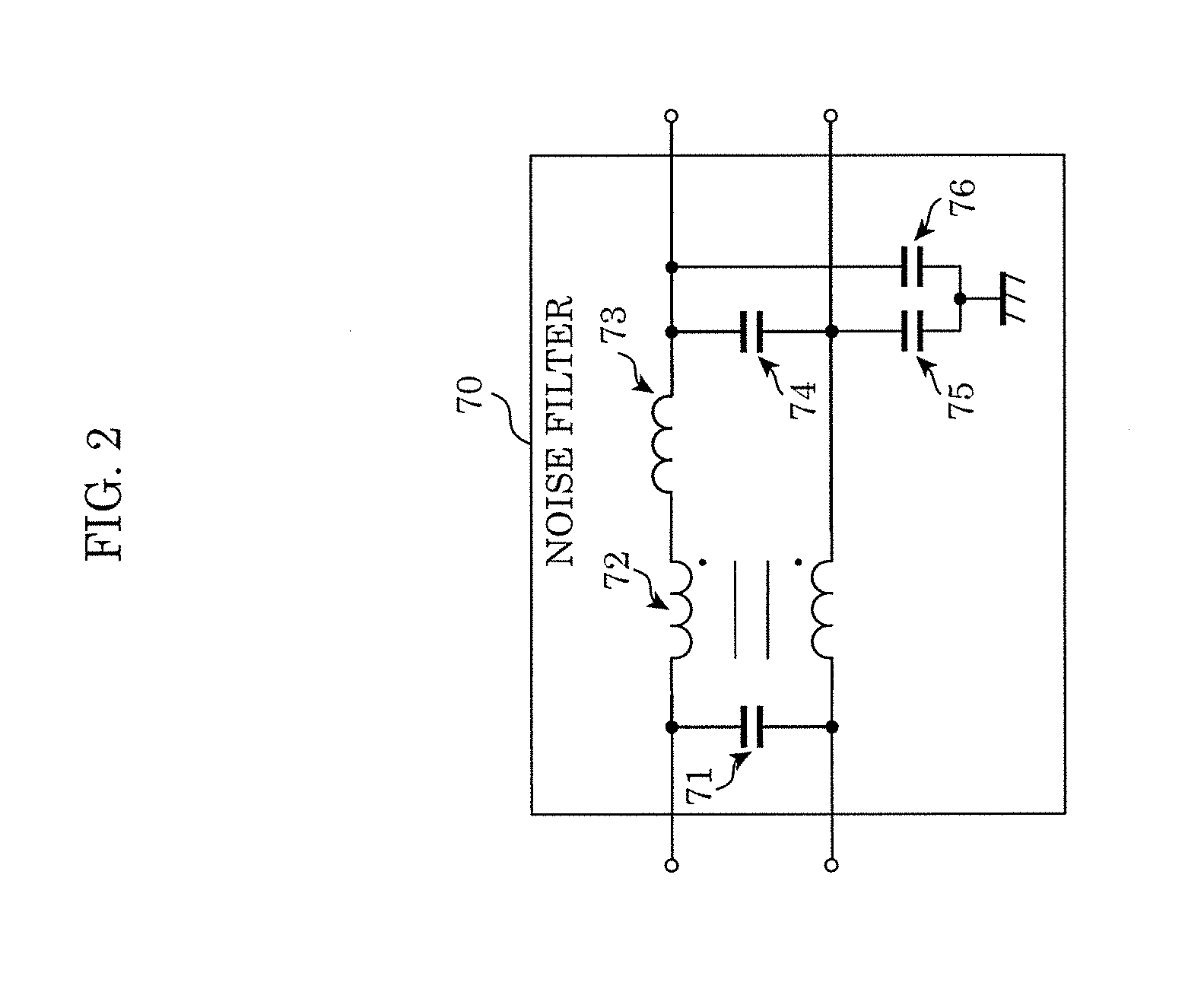
[0032]As illustrated in FIG. 1, lighting apparatus 10 is an apparatus which supplies a current (output current Iout) to LED 14, and includes AC / DC converter 20, detection circuit 30, DC / DC converter 40, and noise filter 70.
[0033]AC / DC converter 20 is a boost chopper type DC power source circuit which converts an alternating-current (AC) voltage to a direct-current (DC) voltage. AC / DC converter 20 converts AC voltage Vac, which is prov...
embodiment 2
[0079]Next, a lighting apparatus according to Embodiment 2 will be described.
[0080]In lighting apparatus 10 according to Embodiment 1 above, the output voltage Vdc is adjusted to make the output voltage Vdc of AC / DC converter 20 and the forward voltage Vf of an LED satisfy the relationship in Expression 2 above. In the present embodiment, the output voltage Vdc is adjusted to make the output voltage Vdc and the forward voltage Vf have a relationship close to the relationship represented by Expression 2 above, though the relationship in Expression 2 is not completely satisfied. With this, in the present embodiment, the configuration of the AC / DC control circuit can be simplified. Hereinafter, description is provided on the reference voltage generating unit of the AC / DC control circuit which is the difference between the present embodiment and Embodiment 1 above. Description on the lighting apparatus and other elements of the present embodiment is omitted.
[2-1. Reference Voltage Gener...
embodiment 3
[0095]Next, a lighting apparatus according to Embodiment 3 will be described.
[0096]Here, an example is indicated which shows that the configuration of the AC / DC control circuit can be further simplified than in Embodiment 2 above. Hereinafter, description is provided on the reference voltage generating unit of the AC / DC control circuit which is the difference between the present embodiment and each of the above-described embodiments. Description on the lighting apparatus and other elements in the present embodiment is omitted.
[3-1. Reference Voltage Generating Unit]
[0097]First, the reference voltage generating unit according to the present embodiment will be described.
[0098]In the same manner as in reference voltage generating unit 200a according to Embodiment 2 above, the reference voltage generating unit according to the present embodiment generates a reference voltage to make the forward voltage Vf and the output voltage Vdc have a relationship close to the relationship in Expres...
PUM
 Abstract
Description
Claims
Application Information