Wire harness fixing structure

a technology of fixing structure and wire harness, which is applied in the direction of insulated conductors, cables, conductors, etc., can solve the problems of affecting the flow of injected cooling medium and damage to the wire harness

Active Publication Date: 2016-03-03
TOYOTA JIDOSHA KK +1
View PDF3 Cites 7 Cited by
  • Summary
  • Abstract
  • Description
  • Claims
  • Application Information

AI Technical Summary

Benefits of technology

[0009]The invention provides a wire harness fixing structure in which a cooling medium injected from a cooling medium relief valve and a wire harness are more reliably prevented from interfering with each other.
[0014]According to the aforementioned aspect of the invention, the wire harness is retained by the retention portion that has the substantially U-shaped form closed at the side facing the cooling medium relief valve. Therefore, the wire harness is effectively prevented from moving toward the cooling medium relief valve. As a result, the cooling medium injected from the cooling medium relief valve and the wire harness can be more reliably prevented from interfering with each other.

Problems solved by technology

As a result, the flow of the injected cooling medium may be hindered, and the wire harness may be damaged.

Method used


Image

  • Wire harness fixing structure
  • Wire harness fixing structure
  • Wire harness fixing structure

Examples


Embodiment Construction

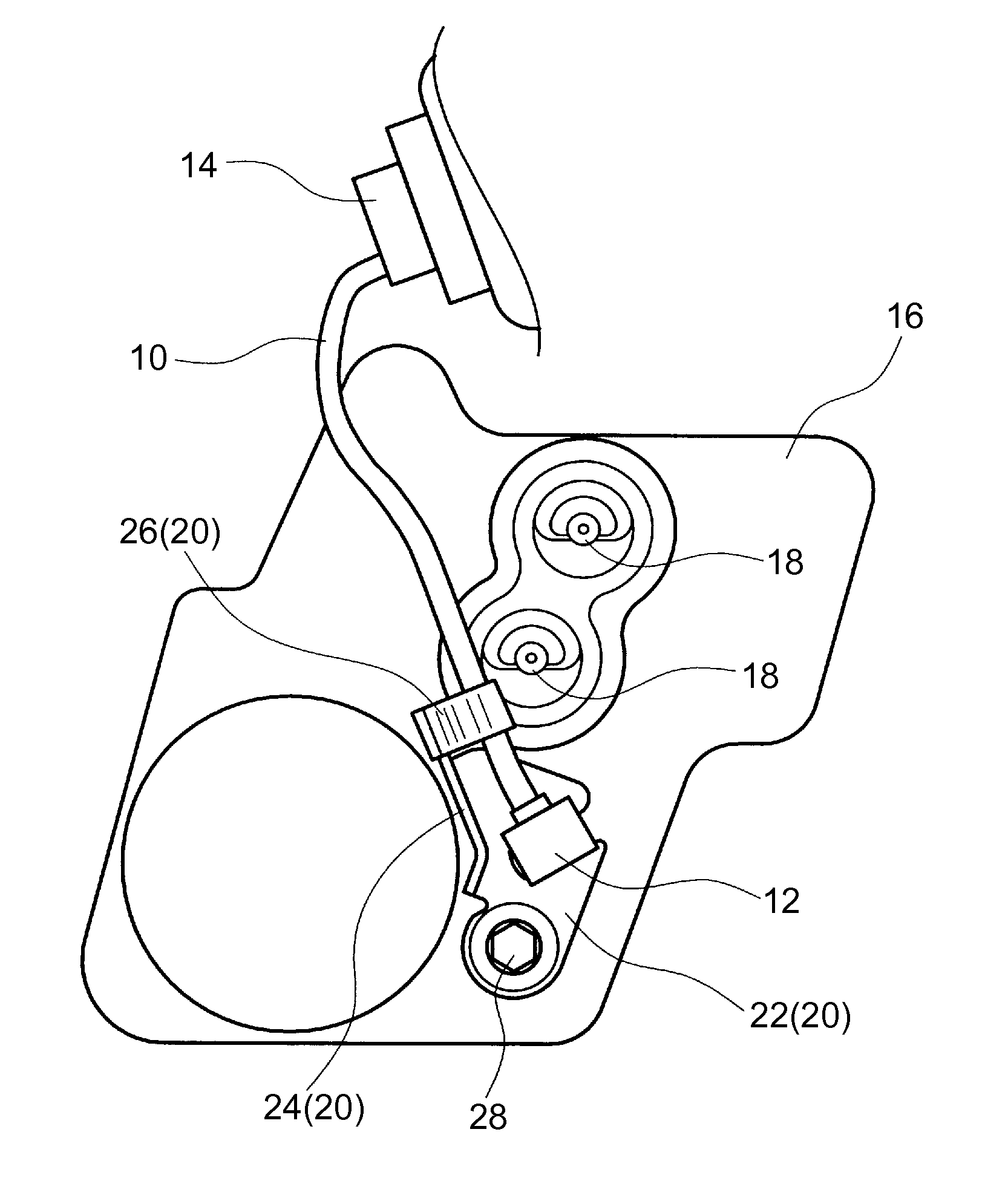
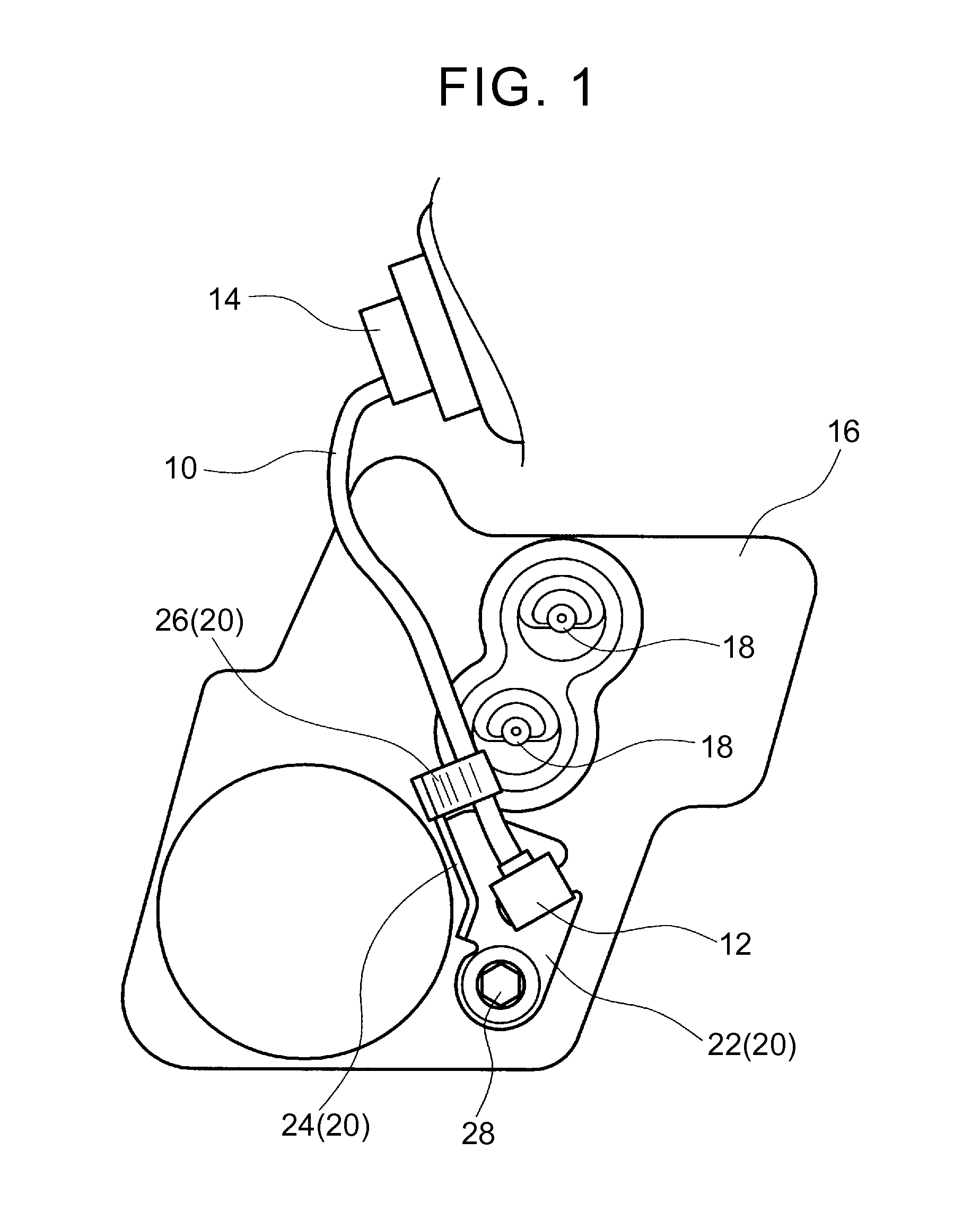
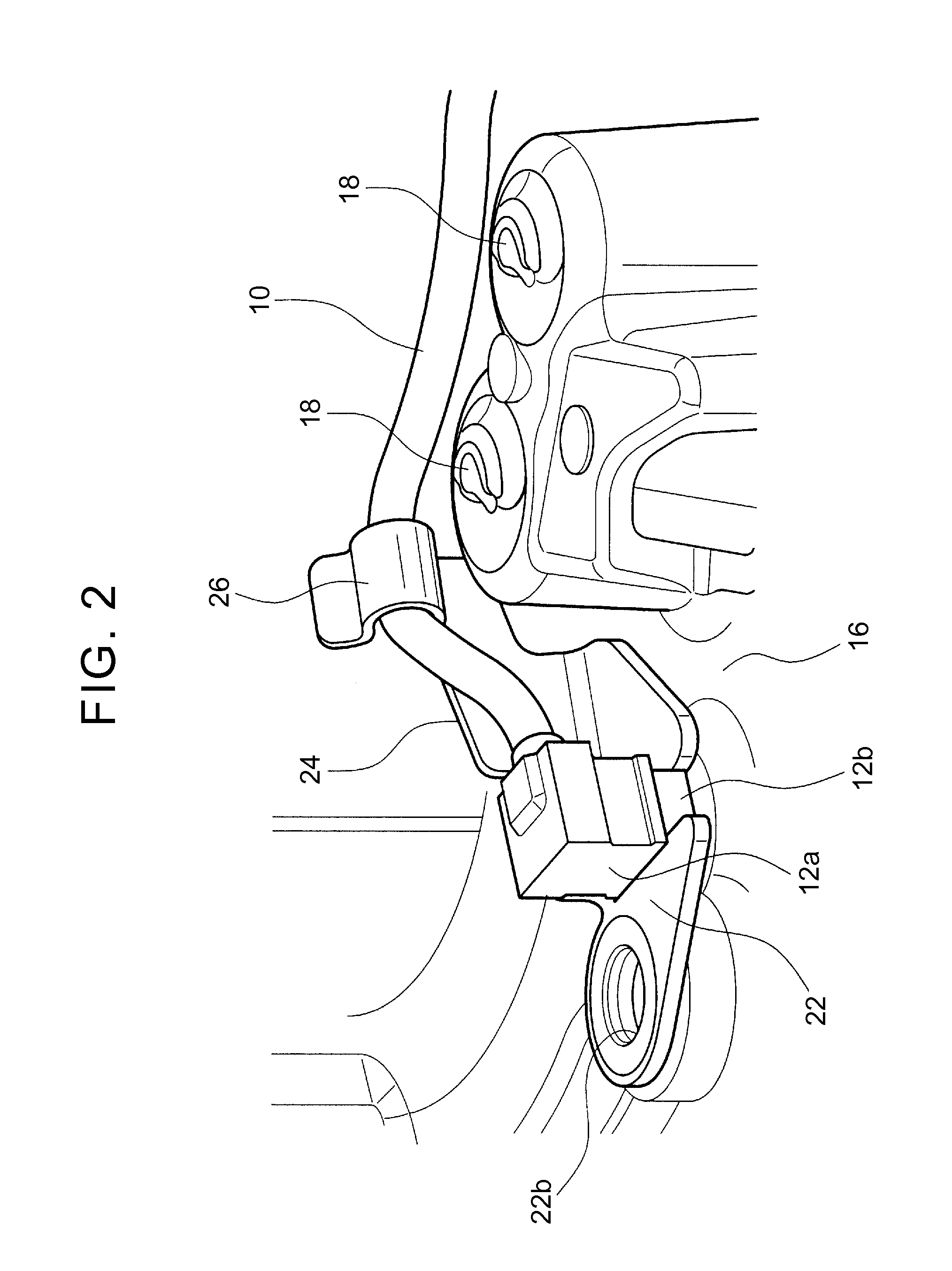
[0021]Embodiment of the invention will be described hereinafter with reference to the drawings. FIG. 1 is a schematic plan view of a cooling medium tank 16 to which a wire harness fixing structure according to an embodiment of the invention is applied, and an area around the cooling medium tank 16. FIG. 2 is a perspective view of the cooling medium tank 16 and the area around the cooling medium tank 16. Some members are not shown in FIG. 1 for the sake of understandability.

[0022]This cooling medium tank 16 stores a cooling medium for cooling a rotating electrical machine that serves as a power source of a hybrid vehicle or an electric vehicle. The cooling medium may be liquid or gas as long as the rotating electrical machine can be thereby cooled. In the present embodiment of the invention, however, cooling oil is adopted as the cooling medium. This cooling medium tank 16 is accommodated in a motor-generator case together with the rotating electrical machine. Cooling medium relief v...


PUM

PropertyMeasurementUnit
fixing structureaaaaaaaaaa
temperatureaaaaaaaaaa
viscosityaaaaaaaaaa

Abstract

A wire harness fixing structure includes a cooling medium tank provided with a cooling medium relief valve; a sensor that is installed in the cooling medium tank; a connection terminal that is located beyond the cooling medium relief valve as viewed from a position where the sensor is installed; a wire harness that electrically connects the sensor to the connection terminal; and a bracket that is fastened to the cooling medium tank and that fixes the wire harness. The bracket includes a fastened portion that is fastened to the cooling medium tank, and a retention portion that has a substantially U-shaped form closed at a side facing the cooling medium relief valve and that retains the wire harness in the U-shaped form.

Description

INCORPORATION BY REFERENCE[0001]The disclosure of Japanese Patent Application No. 2014-172254 filed on Aug. 27, 2014 including the specification, drawings and abstract is incorporated herein by reference in its entirety.BACKGROUND OF THE INVENTION[0002]1. Field of the Invention[0003]The invention relates to a wire harness fixing structure in which a wire harness is fixed, the wire harness electrically connecting a sensor that is installed in a cooling medium tank provided with a cooling medium relief valve, to a connection terminal that is located beyond the cooling medium relief valve as viewed from a position where the sensor is installed.[0004]2. Description of Related Art[0005]Conventionally, in order to cool an object such as a rotating electrical machine, there has been known a cooling structure in which a cooling medium is stored in a tank, and a cooling medium relief valve that is provided in the cooling medium tank is opened to inject the cooling medium onto the object. In ...

Claims


Application Information

Patent Timeline
Patent Type & Authority Applications(United States)
IPC IPC(8): H05K7/20H01B7/00
CPCH01B7/0045H05K7/20281B60R16/0215H02G3/32
Inventor TSUBOI, HIROKITAKEUCHI, TAKETOOGISU, TAKAFUMI
Owner TOYOTA JIDOSHA KK
Why Eureka
Try Eureka