Control device and speed reducer system

a control device and speed reducer technology, applied in the direction of program control, electric programme control, instruments, etc., can solve the problems of high manufacturing cost of a control device incorporating the techniques, unsuitable arrangement of encoders on the output side of speed reducers, and difficulty in adapting to the use of different speed reducers, so as to improve follow-up accuracy

Active Publication Date: 2016-03-10
NAT UNIV CORP NAGAOKA UNIV TECH +1
View PDF5 Cites 22 Cited by
  • Summary
  • Abstract
  • Description
  • Claims
  • Application Information

AI Technical Summary

Benefits of technology

[0008]The present invention aims to provide control techniques f...

Problems solved by technology

Therefore, there is a high manufacturing cost of a control device incorporating the techniques disclosed in JP 2012-122509 A.
On the other hand, there are technical fields in which the arrangement of an encoder on an output side of a speed reducer is not desirable (e.g. technical fields of industrial robots).
Therefore, the techniques disclosed in JP 2012-122509 A face a problem in versatility.
Therefore, the technique...

Method used


Image

  • Control device and speed reducer system
  • Control device and speed reducer system
  • Control device and speed reducer system

Examples


first embodiment

[0044]

[0045]Generally, a speed reducer has transmission characteristics such as elasticity, backlash and angular transmission error. These transmission characteristics worsen operational accuracy of a device incorporating the speed reducer. Wave gear devices and oscillatory cyclo-speed reducers are often used in technical fields such as industrial robots. The wave gear devices and the oscillatory cyclo-speed reducers may transmit power more accurately than general speed reducers.

[0046]An oscillatory cyclo-speed reducer may transmit power at a high speed reduction ratio and has very small backlash. The oscillatory cyclo-speed reducer is small in size and has high rigidity. In view of these characteristics, the oscillatory cyclo-speed reducer is often used for a part of large-size robots and industrial robots for which high rigidity is required.

[0047]An oscillatory cyclo-speed reducer includes annularly arranged internal teeth and an oscillatory gear portion meshed with the internal t...

second embodiment

[0179]The observer described in the context of the first embodiment outputs an axial torsional vibration. Alternatively, the observer may output a vibration component caused by holes which are formed in a gear portion. A speed reducer system including an observer configured to output a vibration component caused by holes which are formed in a gear portion is described in the second embodiment,

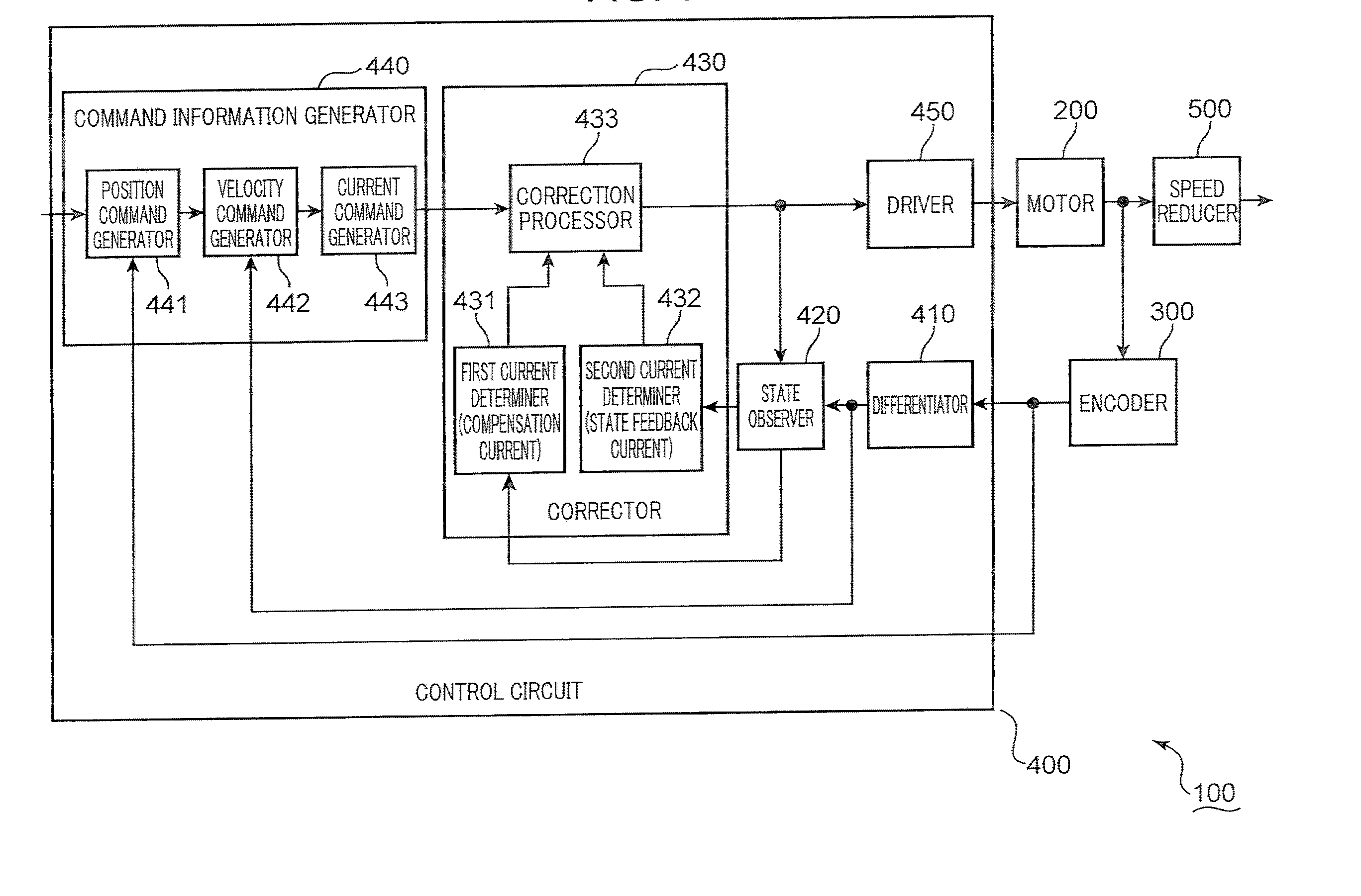
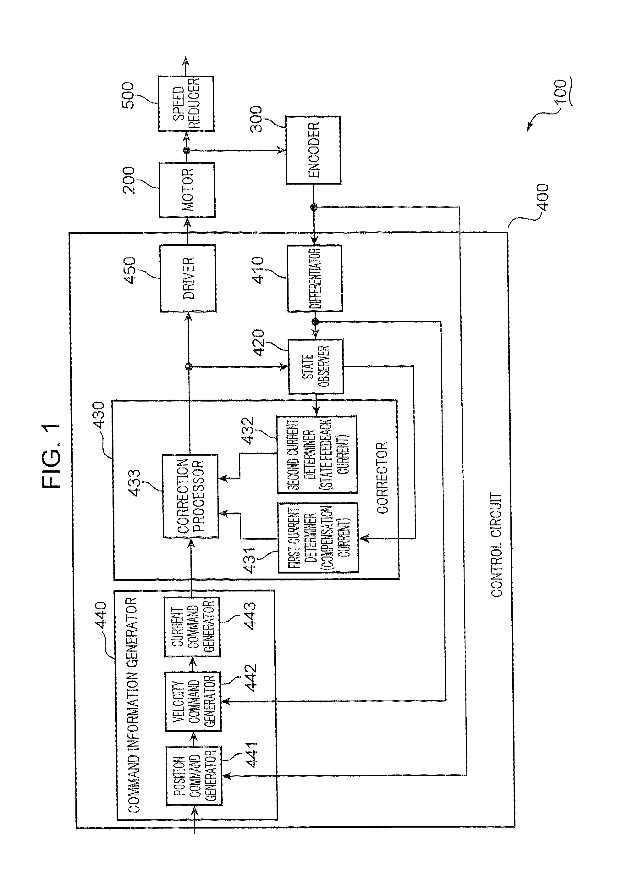
[0180]FIG. 9 is a control block diagram of the speed reducer system 100 (c.f. FIG. 1). Signs and symbols commonly used between the first and second embodiments mean that elements denoted by the common signs and symbols have the same functions as the first embodiment. Therefore, the description of the first embodiment is applicable to these elements. The speed reducer system 100 is described with reference to FIGS. 1, 5 and 9.

[0181]Like the first embodiment, the control block diagram shown in FIG. 9 is divided into an actuator section and a control section. The actuator section shows the motor 2...

third embodiment

[0205]The observers described in the context of the first and second embodiments may estimate an angular error in light of a disturbance torque which rapidly changes like a step function. However, a system incorporating a speed reducer may receive a periodically changing disturbance load. A speed reducer system configured to reduce an angular transmission error even under an environment in which there is a periodically changing disturbance load is described in the third embodiment.

[0206]FIG. 11 is a schematic block diagram showing an exemplificative functional configuration of a speed reducer system 100B. Signs and symbols commonly used in the first and third embodiments mean that elements denoted by the common signs and symbols have the same functions as the first embodiment. Therefore, the description of the first embodiment is applicable to these elements. The speed reducer system 100B is described with reference to FIG. 11.

[0207]Like the first embodiment, the speed reducer syste...


PUM


Abstract

This application discloses a control device for controlling a motor configured to drive an oscillatory cyclo-speed reducer including an oscillatory gear portion formed with at least one hole at an eccentric position. The control device includes an angle acquirer for acquiring input information about an input rotational angle indicating a rotational angle of the motor, an estimator for estimating an angular error between the input rotational angle and an output rotational angle indicating a rotational angle of the oscillatory cyclo-speed reducer based on a quantity of the hole(s) and a corrector for determining a compensation current value in correspondence to the angular error and setting a magnitude of a current to be supplied to the motor by correcting a command current value using the compensation current value.

Description

TECHNICAL FIELD[0001]The present invention relates to control techniques for controlling an oscillatory cyclo-speed reducer.BACKGROUND ART[0002]A reduction in an angular transmission error of a speed reducer is required for a variety of technical fields such as industrial robots and machine tools. Various control techniques have been proposed (cf. JP 2012-122509 A and JP 2003-223225 A) in response to requests for a reduction in the angular transmission error.[0003]JP 2012-122509 A proposes usage of an encoder arranged on an input side of a speed reducer and another encoder arranged on an output side of the speed reducer to reduce an angular transmission error. JP 2003-223225A proposes usage of error correction data acquired in advance to reduce an angular transmission error.[0004]Techniques disclosed in JP 2012-122509 A require a plurality of encoders. Therefore, there is a high manufacturing cost of a control device incorporating the techniques disclosed in JP 2012-122509 A.[0005]T...

Claims


Application Information

Patent Timeline
IPC IPC(8): G05B19/04G05D13/62
CPCG05B19/04G05B2219/25355G05B2219/25052G05D13/62H02P6/16H02P23/04H02P23/12
Inventor OHISHI, KIYOSHIYOKOKURA, YUKIHIRANO, YOSEINAKAMURA, KOJISATO, MASATAKA
Owner NAT UNIV CORP NAGAOKA UNIV TECH
Why Eureka
Try Eureka