Diagnostic unit and method

a diagnostic unit and diagnostic method technology, applied in the field of diagnostic units and methods, can solve the problems of reducing prices, and achieve the effects of accurate identification of mechanical faults, increased computing resources, and increased volume of performance data transmitted

Inactive Publication Date: 2016-03-10
ZONAR SYST
View PDF9 Cites 22 Cited by
  • Summary
  • Abstract
  • Description
  • Claims
  • Application Information

AI Technical Summary

Benefits of technology

[0021]It should be understood that the concepts disclosed herein can be combined with many types of data collection strategies. In at least one embodiment, the vehicle is configured to transmit data to the remote server at various intervals, and at each interval, the vehicle will transmit data including position data and vehicle performance data to the remote server (however, the concepts disclosed herein also encompass embodiments where performance data is transmitted without position data). The quantity of performance data to be transmitted can be varied. The more performance data that is conveyed from the vehicle to the remote server operated by the monitoring service, the more likely the remote server will be able to accurately identify mechanical faults. However, as the volume of performance data transmitted from the vehicle to the remote server increases, the required computing resources increases, and transmission related costs can increase. Thus, the artisan of skill will recognize that tradeoffs exist in determining how much performance data to convey from the vehicle to the remote server. In at least one embodiment, a relatively small amount of performance data is transmitted to the remote server at each transmission interval. The type of data transmitted at each interval can be varied (for example, injector data is included in a first transmission, oxygen sensor data is included in a second transmission, brake sensor data is included in a third transmission, and so on until many different types of performance data are conveyed to the remote server over time). In at least some embodiments, the remote server is configured to request specific types of performance data (i.e., data from specific sensors) to aid in identifying a particular mechanical fault.

Problems solved by technology

In a reverse auction, sellers compete to obtain business, and prices typically decrease over time.

Method used


Image

  • Diagnostic unit and method
  • Diagnostic unit and method
  • Diagnostic unit and method

Examples


Embodiment Construction

Figures and Disclosed Embodiments are not Limiting

[0035]Exemplary embodiments are illustrated in referenced Figures of the drawings. It is intended that the embodiments and Figures disclosed herein are to be considered illustrative rather than restrictive. No limitation on the scope of the technology and of the claims that follow is to be imputed to the examples shown in the drawings and discussed herein. Further, it should be understood that any feature of one embodiment disclosed herein can be combined with one or more features of any other embodiment that is disclosed, unless otherwise indicated.

[0036]As used herein and in the claims that follow, a reference to an activity that occurs in real-time is intended to refer not only to an activity that occurs with no delay, but also to an activity that occurs with a relatively short delay (i.e., a delay or lag period of seconds or minutes, but with less than an hour of lag time).

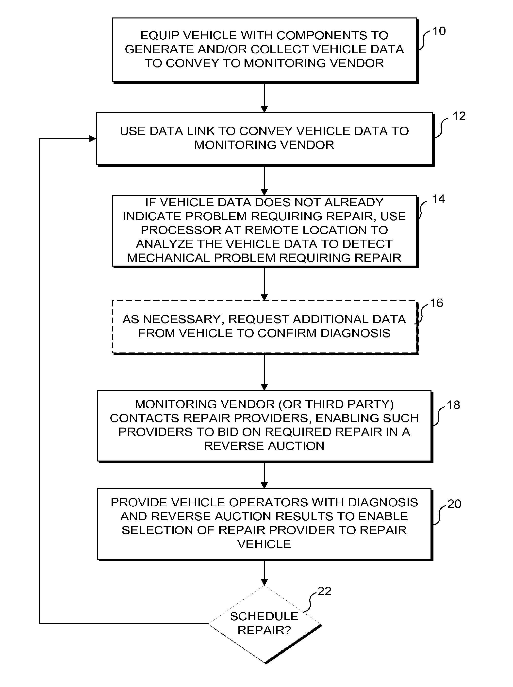
[0037]FIG. 1 is a high level flowchart showing the overal...


PUM


Abstract

A diagnostic unit is coupled to at least one vehicle control subsystem. The vehicle control subsystem includes one or more of a brake control unit, an engine control unit, and a transmission control unit to provide vehicle data. The diagnostic unit generates diagnostic log information based on the vehicle data and communicates the diagnostic log information to a remote computing device, which hosts a reverse auction to identify at least one vendor that can provide vehicle service based on the diagnostic log information. After identifying the vendor, the diagnostic unit generates and presents service information representing the identified vendor to a vehicle operator via an input/output interface in the vehicle. The input/output interface can accept vehicle data, configuration data, and diagnostic data from the vehicle and the vehicle operator.

Description

CROSS-REFERENCE TO RELATED APPLICATIONS[0001]This application is a divisional of and claims priority to U.S. application Ser. No. 12 / 956,961, filed Nov. 30, 2010. Co-pending applications U.S. application Ser. No. 13 / 157,184, filed Jun. 9, 2011; U.S. application Ser. No. 13 / 157,203, filed Jun. 9, 2011; U.S. application Ser. No. 13 / 219,467, filed Aug. 26, 2011; and PCT / US2011 / 062480, filed Nov. 29, 2011; also claim priority to U.S. application Ser. No. 12 / 956,961. All of said applications are hereby incorporated by reference in their entirety.BACKGROUND[0002]1. Technical Field[0003]2. Description of the Related Art[0004]Today's vehicles are equipped with many different types of data collection and processing components. Much of the data collected by the data collection components is used to control the operation of the vehicle. For example, data collected by oxygen sensors is used to control the amount of fuel introduced into the engine, to avoid providing an overly rich fuel mixture ...

Claims


Application Information

Patent Timeline
Patent Type & Authority Applications(United States)
IPC IPC(8): G07C5/08B60K35/00
CPCB60K35/00G07C5/0808G06Q30/0282G06Q30/08G07C5/008
Inventor MCQUADE, CHARLES MICHAELBRINTON, BRETT
Owner ZONAR SYST
Why Eureka
Try Eureka