
System and Method for Inductor Isolation

Active Publication Date: 2016-03-10
INNOPHASE
View PDF7 Cites 16 Cited by
  • Summary
  • Abstract
  • Description
  • Claims
  • Application Information

AI Technical Summary

Benefits of technology

The patent describes a system and method for improving the performance of low-noise amplifiers (LNAs) used in reconfigurable transceivers. The invention involves the use of inductor isolation to reduce power consumption and improve linearity and dynamic range. The patent discusses various embodiments of the system and method, including the use of gm-C BPFs, Q-enhanced BPFs, and configurable LNAs. The technical effects of the invention include improved linearity, reduced power consumption, and better dynamic range. The system and method can be used in various LNA / BPF architectures, such as dual-stage LNAs and linearization circuits.

Problems solved by technology

But the power consumption becomes prohibitive when linearity and maximum operational frequency requirements grow.
However, they have limited application due to the tight trade-off between maximum usable tank Q (˜150) and dynamic range (DR˜85 dB).

Method used


Image

  • System and Method for Inductor Isolation
  • System and Method for Inductor Isolation
  • System and Method for Inductor Isolation

Examples


Embodiment Construction

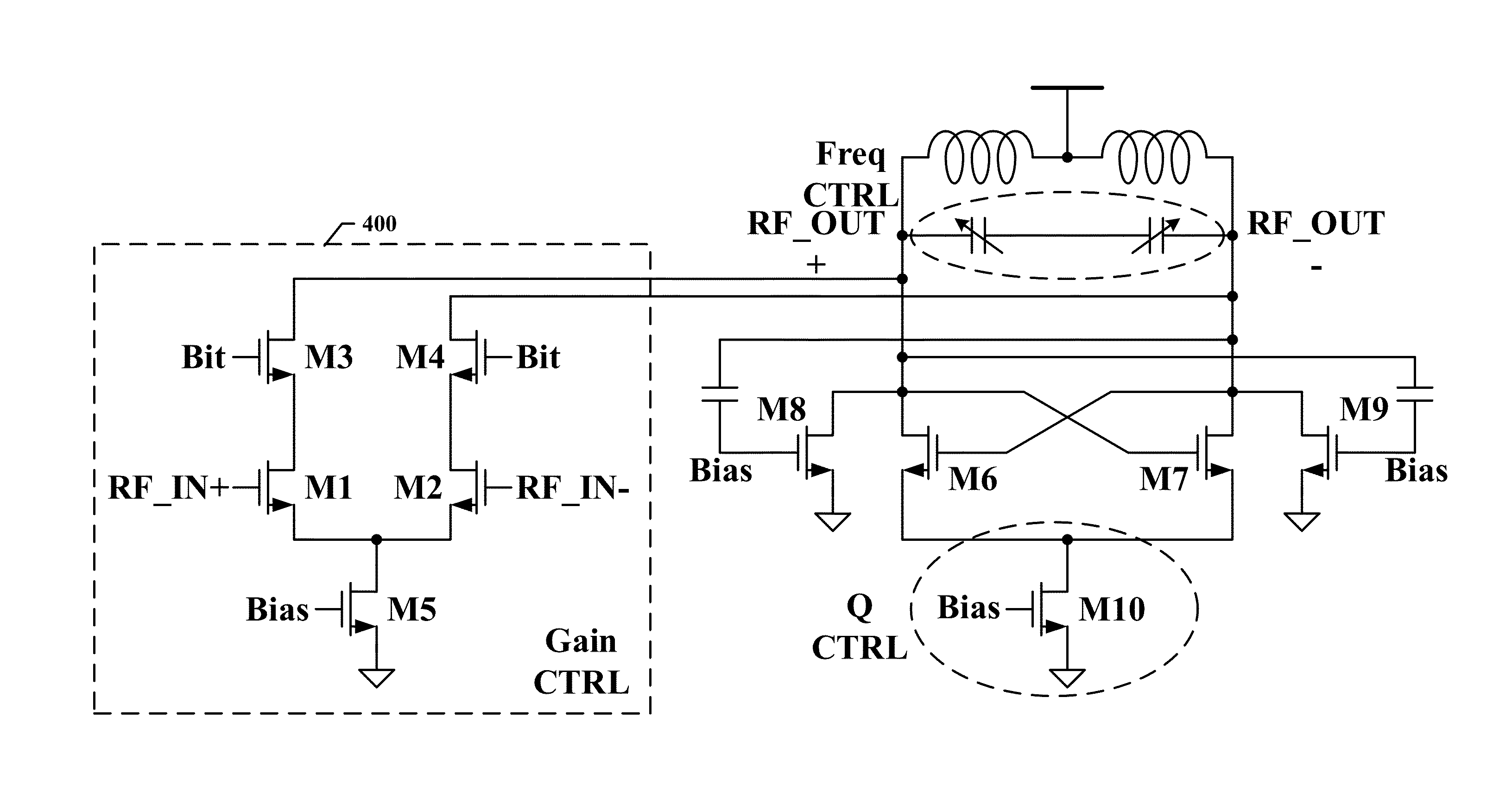
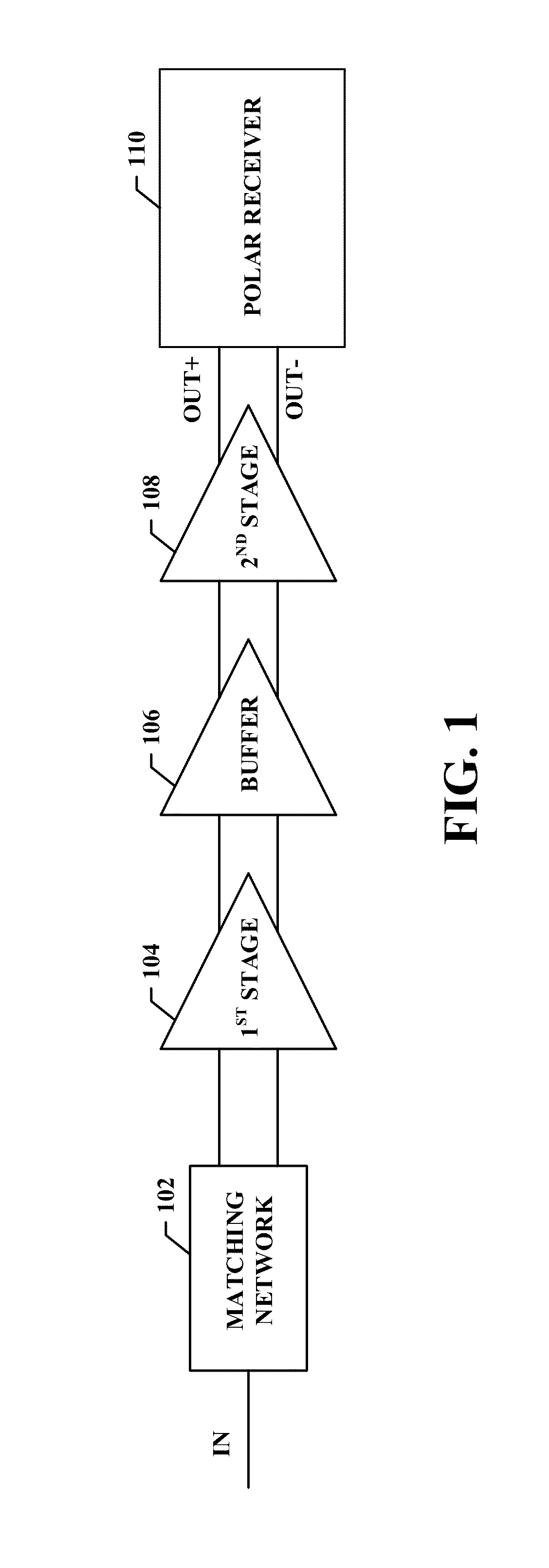
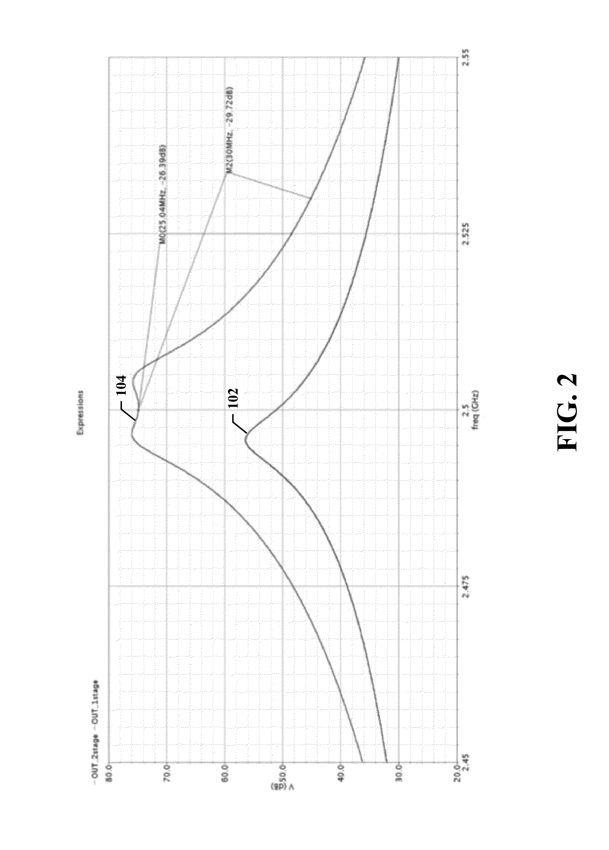
[0027]Disclosed herein is a system and method for inductor isolation. The disclosed system and method is discussed in the context of a low-noise amplifier (LNA) which is sometimes referred to as a bandpass filter (BPF) as it performs frequency filtering. In many of the various embodiments the LNA / BPF includes a plurality of frequency selection circuits which themselves include a respective inductive elements (inductor). A metallization wall surrounds each of the respective inductive elements so as to mitigate feedback and improve isolation between stages of the LNA / BPF. A given metallization wall may surround only the respective inductive element, the entire stage of the LNA / BPF, or a subset of the elements in the LNA / BPS stage that includes the respective inductive element. A single metallization all does not encompass the respective inductive elements of different stages.

[0028]With reference to FIG. 1, an embodiment of a low noise amplifier in accordance with some embodiments will...


PUM


Abstract

An inductor isolation apparatus and method to reduce interaction between inductors on an integrated circuit.

Description

CROSS REFERENCE TO RELATED APPLICATIONS[0001]This application claims the benefit of U.S. Provisional Application No. 62 / 046,710 filed Sep. 5, 2014, reference of which is hereby incorporated herein in its entirety.BACKGROUND OF THE INVENTION[0002]Tunable and highly selective RF filters are used in modern reconfigurable transceivers. On-chip band-pass filters (BPFs) become more attractive than typical off-chip SAW and BAW filters due to their flexibility. Nowadays there are two main approaches to implement on-chip active RF BPFs, namely gm-C BPF and Q-enhanced BPF. The former technique allows a good quality factor with wide tuning range. But the power consumption becomes prohibitive when linearity and maximum operational frequency requirements grow. LC Q-enhanced filters are suitable for GHz applications, and can achieve high quality factors with lower power consumption. However, they have limited application due to the tight trade-off between maximum usable tank Q (˜150) and dynamic ...

Claims


Application Information

Patent Timeline
IPC IPC(8): H03F1/02H03F3/193H03H11/12
CPCH03F1/0205H03H11/12H03F2200/451H03F2200/294H03F3/193H03F1/0261H03F3/191H03F3/195H03F3/45183H03F3/45188H03F3/45475H03F2200/408H03F2203/45138H03F2203/45246
Inventor TESTI, NICOLOXU, YANG
Owner INNOPHASE
Learn More