Image projection apparatus
a projection apparatus and image technology, applied in the direction of picture reproducers using projection devices, static indicating devices, instruments, etc., can solve the problems of more complicated circuits and likely implementation constraints, and achieve the effect of wide brightness range and stable projection of images
- Summary
- Abstract
- Description
- Claims
- Application Information
AI Technical Summary
Benefits of technology
Problems solved by technology
Method used
Image

Examples
example 1
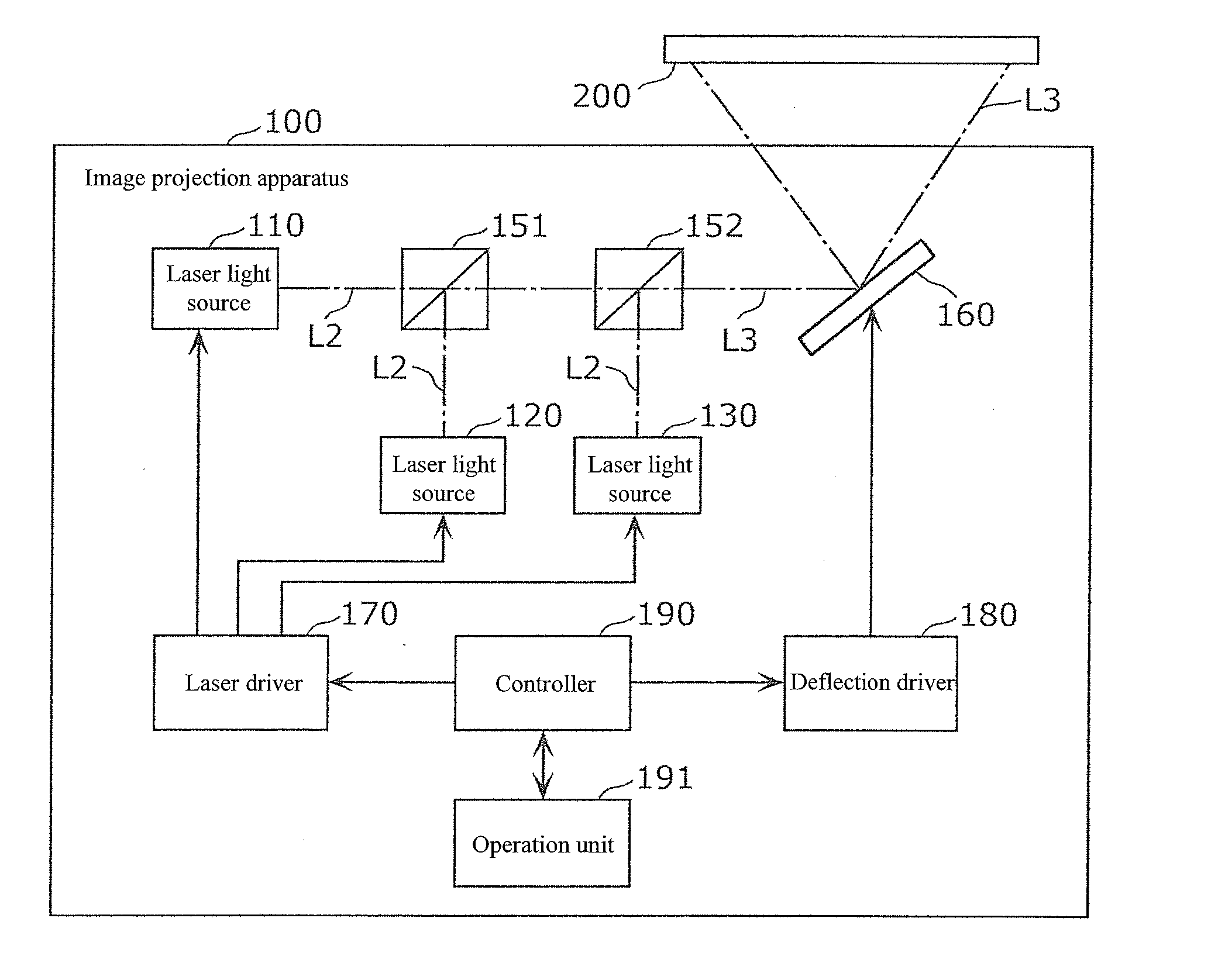
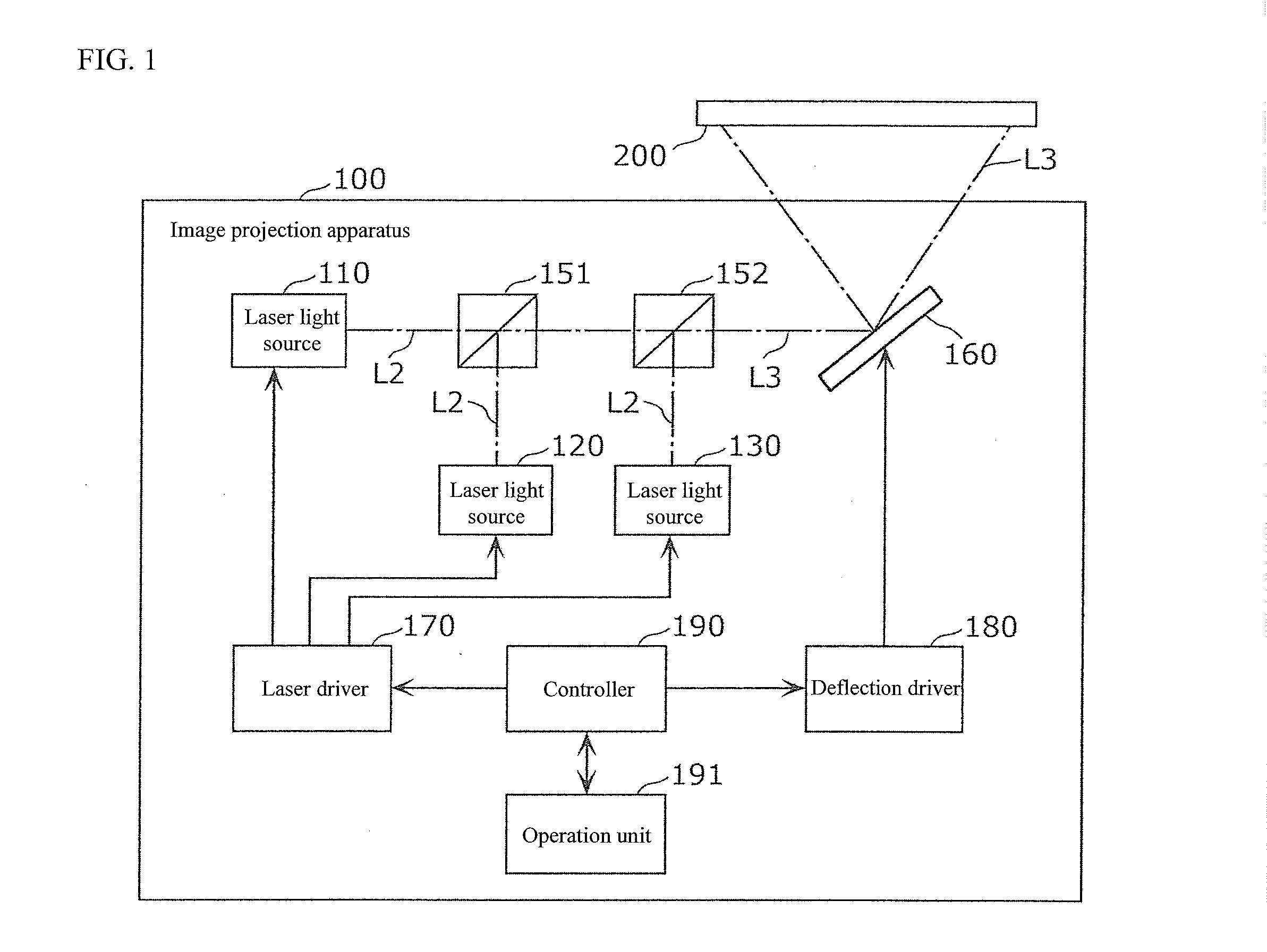
[0067]An image projection apparatus according to one or more embodiments generates a laser light whose intensity is modulated by pixel by a laser light source and projects an image to a screen by scanning the screen with the laser light.
[0068]A plurality of emission points is provided in the laser light source, and the image projection apparatus, when attempting to obtain a laser light of a target intensity, switches between supplying one drive current to a portion of the emission points or distributing the one drive current to every emission point according to whether the target intensity is included in a management range. The management range is defined as a range of the intensity of the laser light obtained when the one drive current is distributed to every emission point and one or more emission points operate in a predetermined unstable region including the mode competition region.
[0069]FIG. 1 is a block diagram illustrating an example of a functional configuration of an image ...
example 2
[0126]In comparison with the image projection apparatus according to Example 1, an image projection apparatus according to Example 2 differs in a configuration of a laser light source.
[0127]FIG. 8 is a block diagram illustrating an example of a functional configuration of a laser light source according to one or more embodiments of the invention. A laser light source 140 illustrated in FIG. 8 replaces the laser light sources 110, 120, 130 of the image projection apparatus 100 according to one embodiments of Example 1.
[0128]The laser light source 140 has a semiconductor chip 145 formed with emission points 141, 142; a collimator lens 114; and a diffraction grid plate 143.
[0129]Each of the emission points 141, 142 emits a first laser light L1 of a wavelength belonging to a color corresponding to the laser light source 140. The emission points 141, 142 may comprise, for example, laser diodes of a multi beam output type as discrete components enclosed in a single package.
[0130]The colli...
example 3
[0137]According to Example 2, an example of the laser light source 140 where the emission points 141, 142; the collimator lens 114; and the diffraction grid plate 143 are disposed in this order in the traveling direction of the laser light is described, but a disposition of the components of the laser light source is not limited to this example. In Example 3, a laser light source whose disposition of components differs is explained.
[0138]FIG. 10 is a diagram illustrating an example of a configuration of a laser light source according to one or more embodiments of the invention.
[0139]As illustrated in FIG. 10, in comparison to the laser light source 140 illustrated in FIG. 8, a laser light source 150 differs in that an ordering of the collimator lens 114 and the diffraction grid plate 143 is reversed. That is, in the laser light source 150, the emission points 141, 142; the diffraction grid plate 143; and the collimator lens 114 are disposed in this order in the traveling direction o...
PUM
 Abstract
Description
Claims
Application Information
 - R&D
- Intellectual Property
- Life Sciences
- Materials
- Tech Scout
- Unparalleled Data Quality
- Higher Quality Content
- 60% Fewer Hallucinations
Browse by: Latest US Patents, China's latest patents, Technical Efficacy Thesaurus, Application Domain, Technology Topic, Popular Technical Reports.
© 2025 PatSnap. All rights reserved.Legal|Privacy policy|Modern Slavery Act Transparency Statement|Sitemap|About US| Contact US: help@patsnap.com