
Console device of portable type, control method and radiographic imaging system

Inactive Publication Date: 2016-03-17
FUJIFILM CORP
View PDF21 Cites 5 Cited by
  • Summary
  • Abstract
  • Description
  • Claims
  • Application Information

AI Technical Summary

Benefits of technology

The invention is a portable console device that improves the recognition of optical images for identification and user menus. It uses a control method and a radiographic imaging system. By overlapping at least partially a radiation image with the first user menu structure, and making the feature portion of the body in the optical image discrete from the second user menu structure without overlap, it provides reliable visual recognition and operability of the user menus.

Problems solved by technology

In the veterinary clinic, an animal owner of an animal (animal body) is checked by interrogation for the identification, as the direct questioning to the animal is impossible.
Thus, a problem arises in that the animal owner cannot check his or her animal directly at the same time as radiographic imaging.
In the emergency medicine, it is likely that the direct questioning of a patient cannot be performed before the image browsing according to impairment of consciousness of the patient.
However, errors may occur in identification.
Possibility of errors is higher in combining the patient IDs in the user page with the patients to be observed actually in the image browsing.
However, the size of a touchscreen display unit of the portable console device useful in the veterinary clinic or for the emergency medicine is smaller than the display panel of the console device of the desktop type.
This makes it difficult to check the identity properly.
Also, the first user menu structure or the second user menu structure must be displayed in a small size, and become difficult to recognize.

Method used


Image

  • Console device of portable type, control method and radiographic imaging system
  • Console device of portable type, control method and radiographic imaging system
  • Console device of portable type, control method and radiographic imaging system

Examples


first embodiment

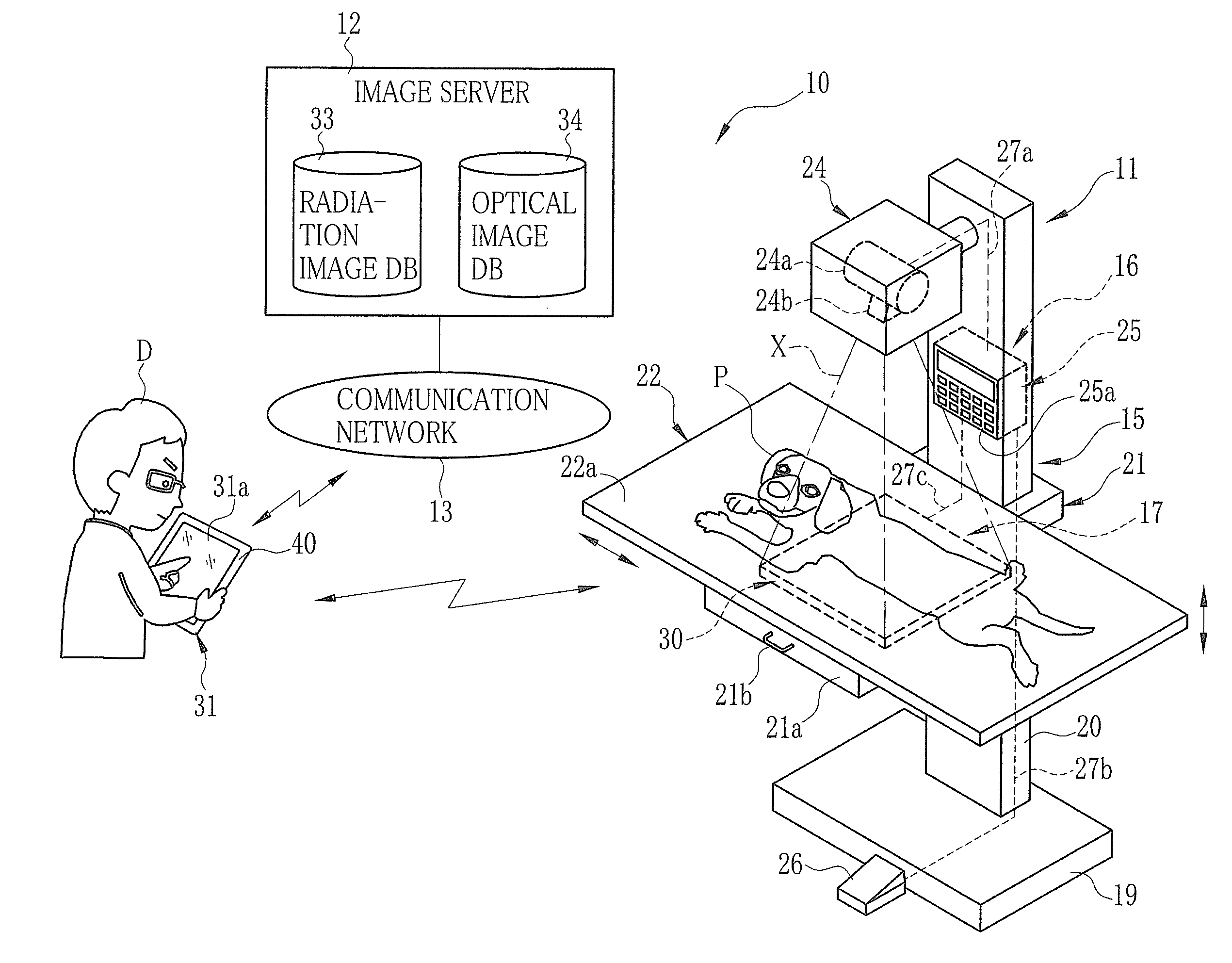
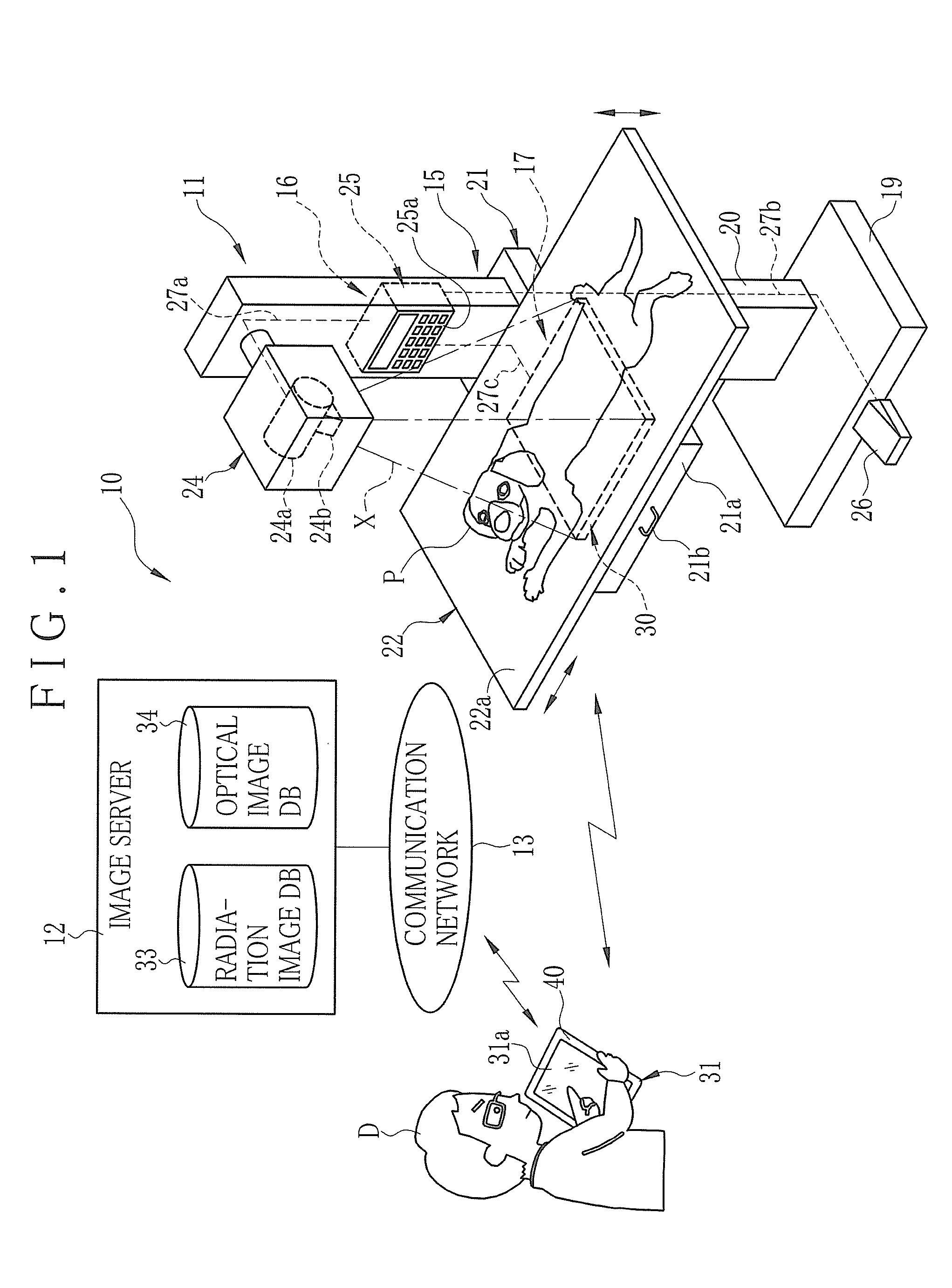
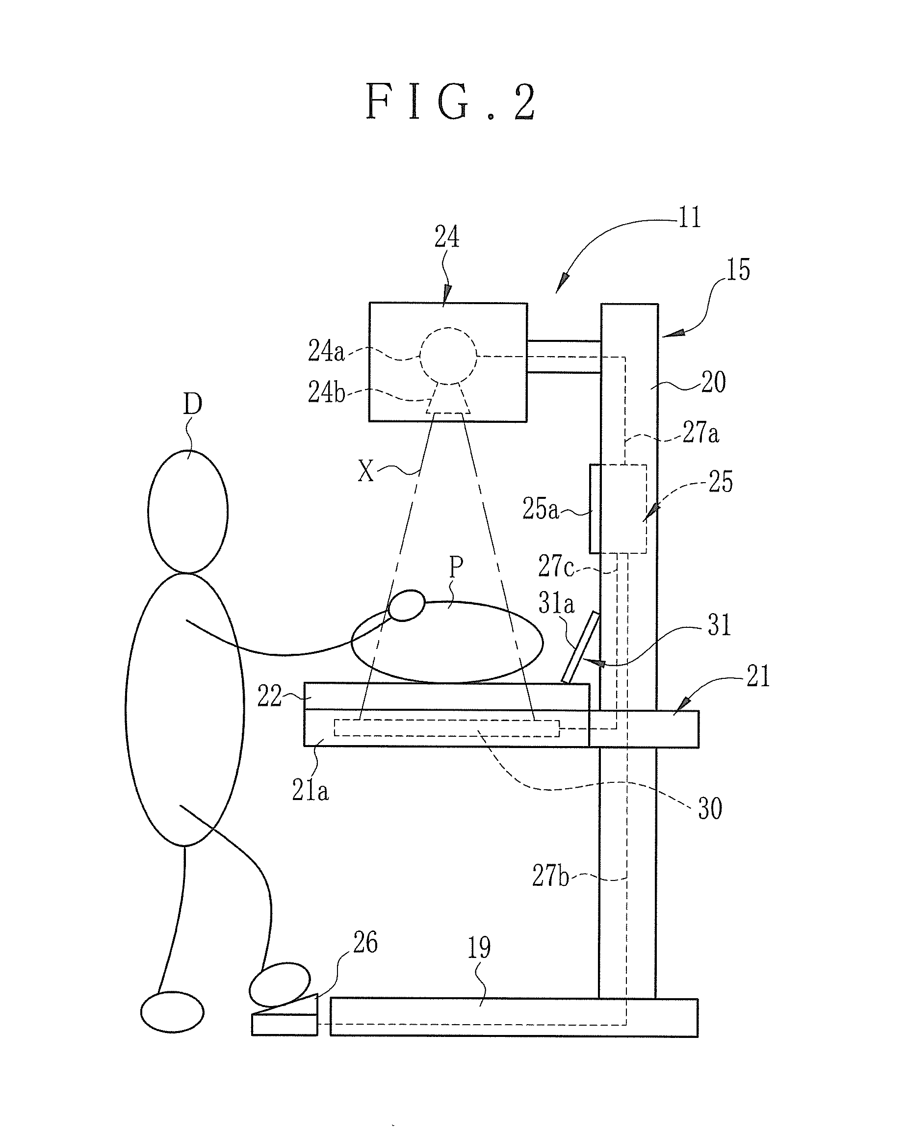
[0069]In FIG. 1, a radiography system architecture 10 or X-ray system architecture for veterinary use is illustrated, and used for imaging of an animal body P of an animal, for example, a dog, cat, and various pets and small animals. The radiography system architecture 10 includes a radiographic imaging system 11 or radiographic imaging apparatus for veterinary use, an image server 12 and a communication network 13. The radiographic imaging system 11 forms a radiation image of the animal body P. The image server 12 manages radiation images of the animal body P. The communication network 13 interconnects the radiographic imaging system 11 and the image server 12 in a communicable manner. An example of the communication network 13 is a local area network (LAN) installed in a veterinary clinic.

[0070]In general, most of the veterinary clinics only have small facilities. Very few veterinary clinics have an electronic medical chart system for the reason of small merit. In the present embo...

second embodiment

[0152]In the first embodiment, an optical image from the optical camera unit 31b is displayed in the user page 56. In a second embodiment, in contrast, a past optical image is acquired from the image server 12 according to a past event of veterinary care. The user page 56 displays the past optical image. In FIGS. 26, 27A and 27B, the optical image acquisition unit 46 transmits a request of distribution to the image server 12 for an image together with a body ID received by the ID reception. In the portable console device 31, an optical image 100 (identification image) searched from the optical image database 34 according to the body ID is received from the image server 12 in the step S21. The display controller 42 causes the user page 56 to display the optical image 100 being received, in the step S22.

[0153]Thus, the optical image 100 of the animal body P can be checked on the portable console device 31 even without newly forming an optical image of the animal body P. Also, the anim...

third embodiment

[0156]In the second embodiment, the optical image 100 from the image server 12 is replaced with the optical image 104 newly photographed by the optical camera unit 31b. In FIG. 28, a third preferred embodiment is illustrated, in which the optical images 100 and 104 are displayed together in the sample window area 59. Also, a status icon 106 (information of graphic expression) can be displayed in an overlapped manner with the optical images 100 and 104 for indicating other undisplayed optical images. Furthermore, it is possible to enlarge and display the optical images 100 and 104 upon manual touch to areas of the optical images 100 and 104. Thus, the use of the optical images can be effective not only for identifying the animal body P but also for medically observing a lesion of injury or skin disease. Note that letters or other graphical expression can be used for indicating other undisplayed optical images in place of the icon.


PUM


Abstract

A console device of a portable type for veterinary use for acquiring a radiation image of an animal body is provided. A display controller outputs a user page for displaying a first user menu structure for acquiring the radiation image and a second user menu structure for acquiring an optical image of the animal body in a list form, the radiation image acquired by use of the first user menu structure, and the optical image acquired by use of the second user menu structure, to control a display unit to display the user page. The display controller processes the user page to display the first user menu structure in an at least partially overlapped manner with the radiation image, and to display the second user menu structure without overlap with a feature portion in the optical image where at least the animal body is recognizable.

Description

CROSS-REFERENCE TO RELATED APPLICATION[0001]This application claims priority under 35 USC 119 from Japanese Patent Application No. 2014-187304, filed 16 Sep. 2014, the disclosure of which is incorporated by reference herein.BACKGROUND OF THE INVENTION[0002]1. Field of the Invention[0003]The present invention relates to a console device of a portable type, a control method and a radiographic imaging system. More particularly, the present invention relates to a console device of a portable type in which visual recognition of an optical image for identification is improved, and visual recognition and operability of the user menus are improved, and a control method and a radiographic imaging system.[0004]2. Description Related to the Prior Art[0005]In the field of medicine, image diagnosis is performed by acquiring medical images of a patient. To this end, a radiographic imaging system for use with radiation such as X-rays is well-known as a system for acquiring medical images. The radi...

Claims


Application Information

Patent Timeline
IPC IPC(8): A61B6/00G06F3/041G06F3/0482G06F3/0485G16H30/20
CPCA61B6/465A61B6/508G06F3/0485G06F3/0482G06F3/041A61B6/467G16H40/63G16H30/20
Inventor OHASHI, YOSUKEOKUSU, KIYOHISAOKABE, YUKI
Owner FUJIFILM CORP
Learn More