Portal imaging during radiotherapy

a technology of portal imaging and radiotherapy, applied in the field of methods, can solve the problems of cell death, limited new use, and small field size of current epids

Active Publication Date: 2016-03-17
ELEKTA AB
View PDF2 Cites 2 Cited by
  • Summary
  • Abstract
  • Description
  • Claims
  • Application Information

AI Technical Summary

Benefits of technology

[0011]Accordingly, the EPID can be moved during the treatment in order to maintain the collimated field of the radiation beam within the bounds of the EPID. This ensures that the image is valid and prevents damage to the EPID as a result of exposure of more sensitive (or less shielded) parts to the beam. No restrictions need be placed on the positioning of the patient, meaning that she or he can be positioned as desired. The treatment can be unaffected, unlike the suggestion made in US2007 / 0195936A1.

Problems solved by technology

The radiation interferes with cellular processes within the tumour and can lead to cellular death.
However, these new uses do have a limitation in that the field size of current EPIDs is smaller than the field sizes of most MLCs.
This is rarely a problem in obtaining an image of the treatment, however, because large field sizes are uncommon and so will usually fall onto the panel within its limits.

Method used


Image

  • Portal imaging during radiotherapy
  • Portal imaging during radiotherapy
  • Portal imaging during radiotherapy

Examples


Embodiment Construction

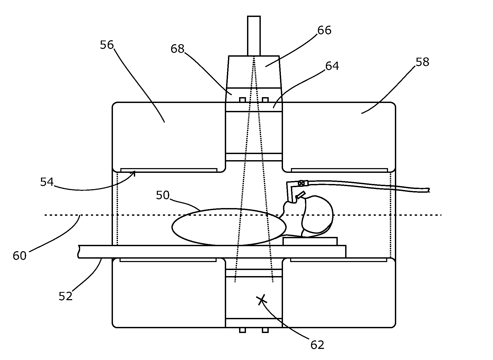
[0024]As noted above, the field size of current EPIDs is smaller than the maximum apertures of most MLCs, although larger than most actual dose shapes. We have realised that this limitation becomes a problem when the EPID is used for portal dosimetry or to capture a dynamic MLC video under certain treatment conditions. As an example, we propose to discuss a volumetric modulated arc therapy (VMAT) delivery to an off-axis target such as a tumour present in one breast or lung. This is not the only example, however, and the invention is applicable in other contexts.

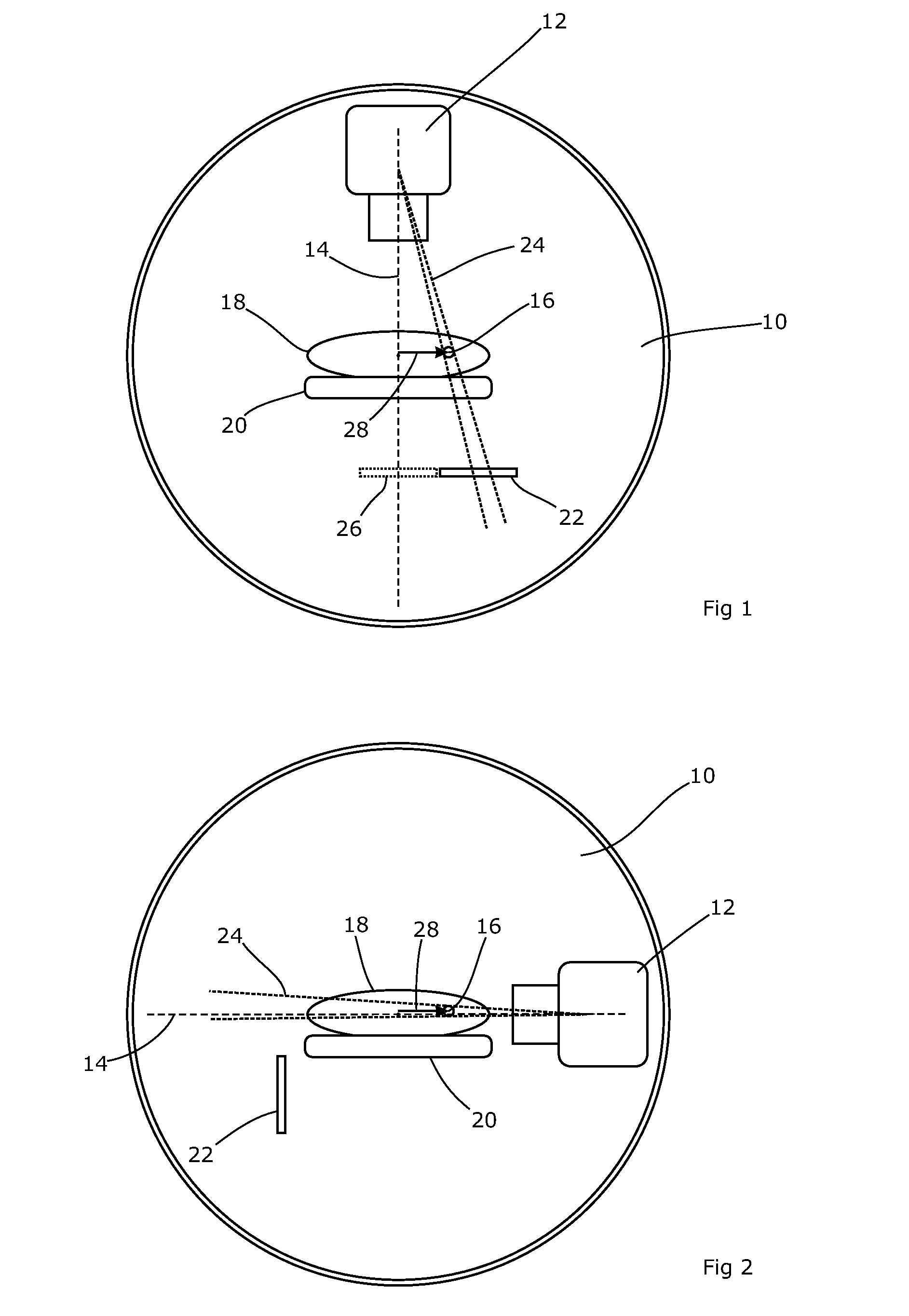
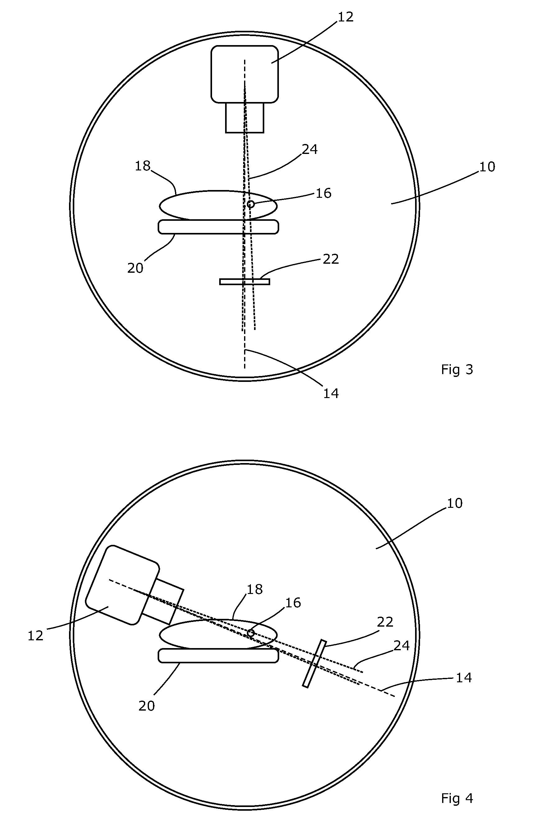
[0025]FIG. 1 shows such a situation. A rotatable gantry 10 is set in an upright orientation, perhaps recessed into a wall or projecting through a false wall. It is in the form of a drum, rotatable around a horizontal axis; FIG. 1 is a view along that axis. The gantry 10 carries a radiation source 12 which can emit a collimated beam of therapeutic ionising radiation around a central axis 14, which intersects with the horizonta...


PUM


Abstract

A radiotherapy apparatus comprises a source for producing a beam of ionising radiation along an axis, the beam covering a maximum aperture of the source, a collimator for collimating the beam to produce a collimated beam covering a sub-part of the maximum aperture, a patient support positioned in the path of the beam, a rotatable gantry, on which the source is mounted, for rotating the source around the patient support thereby to deliver the beam from a range of directions, an imaging device located opposite the source and with the patient support between the source and the imaging device, and mounted on the gantry via a drive member allowing translational motion of the imaging device in at least one direction perpendicular to the axis, and a control unit adapted to control the drive member to move the imaging device within the maximum aperture and maintain coincidence between the imaging device and the sub-part of the maximum aperture. Accordingly, the EPID can be moved during the treatment in order to maintain the collimated field of the radiation beam within the bounds of the EPID. This ensures that the image is valid and prevents damage to the EPID as a result of exposure of more sensitive (or less shielded) parts to the beam.

Description

FIELD OF THE INVENTION[0001]The present invention seeks to improve upon existing methods of portal imaging during radiotherapy treatment.BACKGROUND ART[0002]Radiotherapy is the treatment of lesions such as tumours with ionising radiation such as high-energy x-rays. The radiation interferes with cellular processes within the tumour and can lead to cellular death. To spare healthy tissue (such as skin or organs adjacent to the tumour, or through which the radiation needs to pass in order to treat the tumour), shaped radiation beams are aimed from several different angles to intersect at the tumour, thus delivering a peak dose in the tumour region and a lower dose elsewhere.[0003]To allow delivery of the radiation from several angles, the radiation source is usually mounted on the end of a cantilever arm projecting out from a rotatable gantry. The gantry has an axis of rotation that is horizontal, and the radiation source has a field of view whose central axis is perpendicular to and i...

Claims


Application Information

Patent Timeline
Patent Type & Authority Applications(United States)
IPC IPC(8): A61N5/10
CPCA61N5/1049A61N5/1081A61N5/1047A61N2005/1054A61N5/1036A61N5/1083A61N2005/1074A61N5/107A61B6/032
Inventor ALLEN, JOHNWINFIELD, COLIN
Owner ELEKTA AB
Why Eureka
Try Eureka