Die cushion device and control method of die cushion device

a technology of die cushion and control method, which is applied in the direction of forging press details, manufacturing tools, forging presses, etc., can solve the problems of large energy loss, increase in power cost and cooling cost (electricity cost), and many problems of the die cushion device, so as to improve the efficiency of press forming, increase the size of the device, and increase the effect of the device pri

Active Publication Date: 2016-03-17
AIDA ENG LTD
View PDF4 Cites 7 Cited by
  • Summary
  • Abstract
  • Description
  • Claims
  • Application Information

AI Technical Summary

Benefits of technology

[0032]According to the present invention, it is possible to perform pressure control of a cushion pad during a rising process of a slide of a press machine to enable press forming during the pressure control without resulting in an increase in size of a device and resulting in a high price of the device. As a result, two times of press forming per one press cycle can be achieved to enable efficiency of the press forming to be improved.

Problems solved by technology

In addition, since in each of the die cushion process and the rising process, pressure is controlled by throttling pressure oil using the servo valve to control the amount of oil, there is a large energy loss so that power cost and cooling cost (electricity cost) increase.
That is, also in the relatively simple servo die cushion device of a servo valve system described in Patent Application Laid-Open No. 2006-142312, in a case where forming requiring relatively large force is performed in the rising process, the die cushion device accompanies many problems, such as increase in capacity of a device, energy loss, and useless cycle time.
In Japanese Patent Application Laid-Open No. 2006-315074, however, there is no description of press forming that is to be performed during a rising process, and is no disclosure of an idea of performing press forming during each of the die cushion process (lowering process) and the rising process.

Method used


Image

  • Die cushion device and control method of die cushion device
  • Die cushion device and control method of die cushion device
  • Die cushion device and control method of die cushion device

Examples


first embodiment

of Die Cushion Device

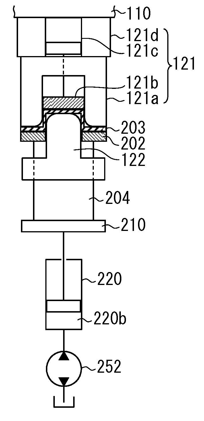
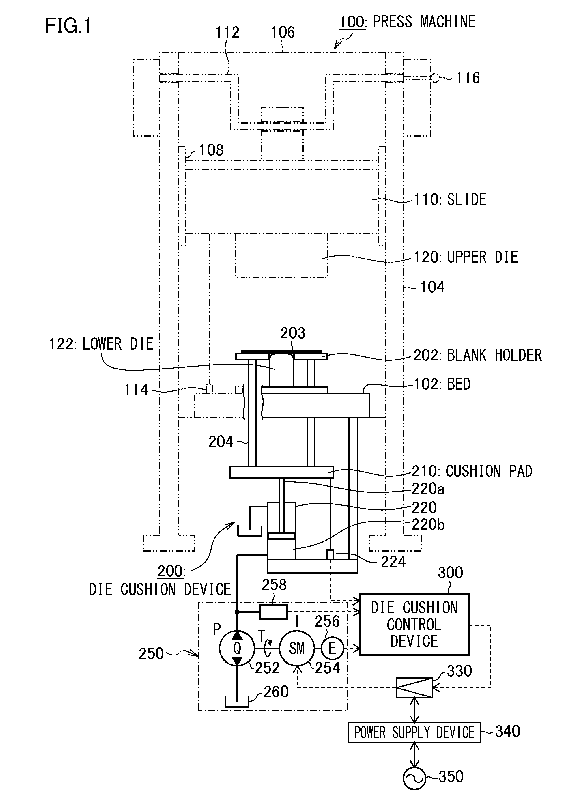
[0041]FIG. 1 is a structural view showing a first embodiment of a die cushion device in accordance with the present invention. In FIG. 1, a press machine 100 is shown by a dashed-two dotted line, and a die cushion device 200 is shown by a solid line.

[0042]The press machine 100 shown in FIG. 1 includes a frame that is composed of a bed 102, a column 104, and a crown 106, and a slide 110 that is movably guided in a vertical direction by a guide section 108 provided in the column 104. The slide 110 is moved in a vertical direction in FIG. 1 by a crank mechanism including a crankshaft 112 to which rotational driving force is transmitted by drive means (not shown).

[0043]The press machine 100 is provided on its bed 102 side with a slide position detector 114 that detects a position of the slide 110, and the crankshaft 112 is provided with a crankshaft encoder 116 that detects each of an angular speed and an angle of the crankshaft 112.

[0044]An upper die 121 is mounted...

second embodiment

of Die Cushion Device

[0111]FIG. 7 is a structural view showing a second embodiment of a die cushion device in accordance with the present invention. A portion common to that shown in FIG. 1 is designated by the same reference numeral as that of FIG. 1 without duplicated description in detail.

[0112]As shown in FIG. 7, a die cushion device 200′ of the second embodiment is different from the die cushion device 200 of the first embodiment shown in FIG. 1 in a configuration of a hydraulic machine (hydraulic machine) 250′ that supplies pressure oil to the hydraulic cylinder 220.

[0113]That is, in the hydraulic machine 250′ used in the die cushion device 200′ of the second embodiment, instead of the electric servo motor 254 of the first embodiment, a both tilting variable capacitor type hydraulic (hydraulic) pump / motor 270 is coupled to a drive shaft of the hydraulic pump / motor 252.

[0114]In addition, an accumulator 272 is connected to a one side port of the both tilting variable capacitor t...


PUM

PropertyMeasurementUnit
pressureaaaaaaaaaa
pressure detectoraaaaaaaaaa
forceaaaaaaaaaa

Abstract

There are provided position controllers each of which controls a position of a cushion pad by controlling a hydraulic machine that supplies pressure oil to a die cushion pressure generation chamber of a hydraulic cylinder, and pressure controllers each of which controls pressure in the die cushion pressure generation chamber of the hydraulic cylinder, and in particular, during a rising process of a slide of a press machine, position control by the position controller and pressure control by the pressure controller are switched to enable press forming also during the rising process.

Description

BACKGROUND OF THE INVENTION[0001]1. Field of the Invention[0002]The present invention relates to a die cushion device and a control method of the die cushion device, and more particularly to a die cushion device and a control method of the die cushion device in which a cushion pad is moved up and down by using a hydraulic cylinder.[0003]2. Description of the Related Art[0004]Heretofore, this kind of die cushion devices are described in Japanese Patent Application Laid-Open No. 2006-142312 and Japanese Patent Application Laid-Open No. 2006-315074.[0005]The die cushion device described in Patent Application Laid-Open No. 2006-142312 is a typical hydraulic servo die cushion device in which die cushion force is generated by using a proportion flow control valve (servo valve), and is composed of very simple components in a system using a servo valve.[0006]In a die cushion process, in a state where an electromagnetic changeover valve is turned off (closed), hydraulic oil displaced from a ...

Claims


Application Information

Patent Timeline
Patent Type & Authority Applications(United States)
IPC IPC(8): B21D24/02
CPCB21D24/02B21D24/10B21D24/14
Inventor KOHNO, YASUYUKI
Owner AIDA ENG LTD
Why Eureka
Try Eureka