Pulse processing circuit with correction means

a processing circuit and correction means technology, applied in the field of pulse processing circuits, can solve the problems of affecting the detection accuracy of photons, so as to achieve the effect of more accurate detection of photons

Inactive Publication Date: 2016-03-17
KONINKLJIJKE PHILIPS NV
View PDF23 Cites 9 Cited by
  • Summary
  • Abstract
  • Description
  • Claims
  • Application Information

AI Technical Summary

Benefits of technology

[0009]Based on this background it would be desirable to provide means that allow for a more accurate detection of photons, particularly of high-energy photons such as X-ray or gamma photons.

Problems solved by technology

One problem such detectors have to cope with is the pile-up or overlap of subsequent pulses in case of high count rates.
Another problem is the splitting of generated charges between neighboring pixels.
Both effects lead to erroneous interpretations in terms of counting rates and / or photon energy.

Method used


Image

  • Pulse processing circuit with correction means
  • Pulse processing circuit with correction means
  • Pulse processing circuit with correction means

Examples


first embodiment

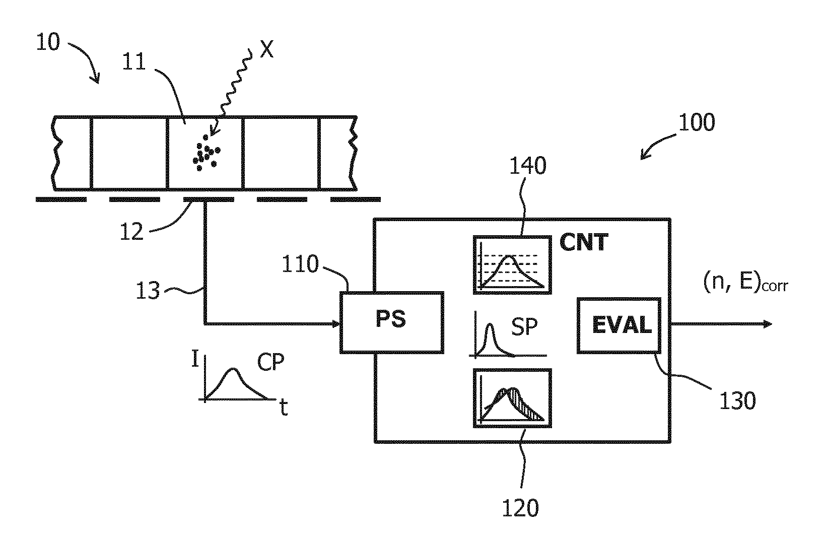
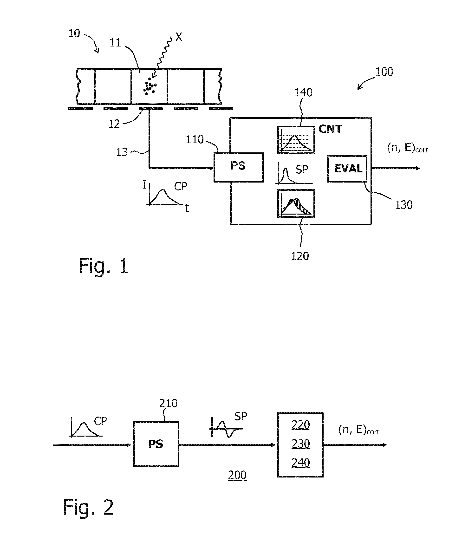
[0063]In FIGS. 2-5, a first embodiment is illustrated that is particularly suited for dealing with the problem of pulse pile-up at high count rates. FIG. 2 schematically shows the associated pulse processing circuit 200, for example realized as an ASIC. The pulse processing circuit 200 includes a CSA (not shown) followed by a specific pulse shaper 210 that transforms the original current pulse CP into a shaped pulse SP.

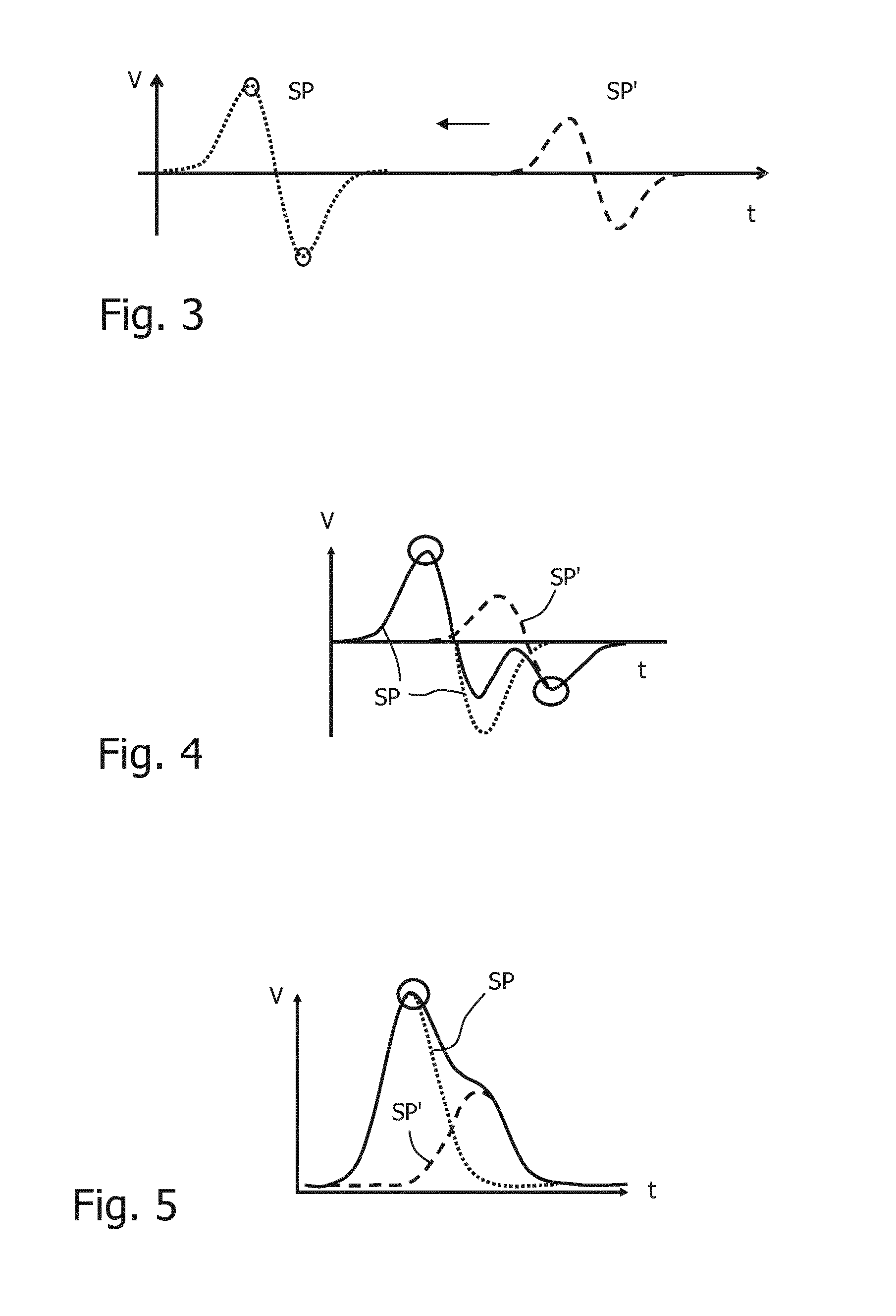
[0064]The shaped pulse SP is forwarded to an integrated spectral counting and correction module 220, 230, 240 comprising several comparators with the possibility to apply positive or negative thresholds. The combination of CSA and pulse shaper is capable to produce bipolar pulses SP with comparable positive and negative pulse heights. Furthermore, a logic unit processing the comparator signals and a data storage unit are included. The logic should be able to determine the number of events contributing to one pulse train and to identify the pulse heights.

[0065]A centra...

second embodiment

[0073]FIGS. 6-11 illustrate the invention that is particularly suited to deal with charge sharing. “Bad” current pulses (affected by charge sharing) differ from “good” ones (not affected) by the current pulse envelopes, meaning that also shaped pulses will show different heights and different timings with respect to the current pulse maximum. The basic idea of this embodiment is to use a pulse shaper ensemble 310 with two individual pulse shapers 310a, 310b per pixel instead of one, each individual pulse shaper having different pulse shaping properties (e.g. different timing constants or different shaping envelopes). Each incoming current pulse thus creates two shaped pulses SP1 and SP2 with different pulse shapes. Also, the shaped pulse maxima might show a time difference to each other. An associated detection module 320 can then use the ratio of the shaped pulse heights and / or their time difference to distinguish “good” pulses from “bad” pulses. Moreover, one of the shaped pulses ...


PUM


Abstract

The invention relates to a method and a pulse processing circuit (100) for the processing of current pulses (CP) generated by incident photons (X) in a piece of converter material, for instance in a pixel (11) of a radiation detector. Deviations of the pulse shape from a reference are detected and used to identify pulse corruption due to pile-up effects at high count rates and/or charge sharing between neighboring pixels. The deviation detection may for instance be achieved by generating, with a pulse shaper (110), bipolar shaped pulses from the current pulse (CP) and/or two shaped pulses of different shapes which can be compared to each other.

Description

FIELD OF THE INVENTION[0001]The invention relates to a method and a pulse processing circuit for counting current pulses that were generated by photons in a piece of converter material.BACKGROUND OF THE INVENTION[0002]Medical imaging apparatuses with spectrally resolved photon counting apply radiation detectors that can count the number of (typically X-ray or gamma) photons hitting the pixels of the detector and that can classify them according to their energy. This is usually achieved by converting the photons into charge, current and / or voltage pulses that can readily be counted, wherein the pulse height or integral indicates the photon energy.[0003]One problem such detectors have to cope with is the pile-up or overlap of subsequent pulses in case of high count rates. Another problem is the splitting of generated charges between neighboring pixels. Both effects lead to erroneous interpretations in terms of counting rates and / or photon energy.[0004]The U.S. Pat. No. 4,658,216 discl...

Claims


Application Information

Patent Timeline
Patent Type & Authority Applications(United States)
IPC IPC(8): G01J1/44
CPCG01J1/44G01T1/171G01T1/24G01T1/247
Inventor DAERR, HEINERENGEL, KLAUS JUERGENHERRMANN, CHRISTOPHSTEADMAN BOOKER, ROGERROESSL, EWALD
Owner KONINKLJIJKE PHILIPS NV
Why Eureka
Try Eureka