Light emitting apparatus and lighting apparatus

Inactive Publication Date: 2016-03-17
PANASONIC INTELLECTUAL PROPERTY MANAGEMENT CO LTD
View PDF8 Cites 15 Cited by
  • Summary
  • Abstract
  • Description
  • Claims
  • Application Information

AI Technical Summary

Benefits of technology

[0010]According to the present disclosure, a light emitting apparatus in which flaking of a dam

Problems solved by technology

Thus, it is a challenge to suppress flaking of the dam mate

Method used


Image

  • Light emitting apparatus and lighting apparatus
  • Light emitting apparatus and lighting apparatus
  • Light emitting apparatus and lighting apparatus

Examples


embodiment 1

Configuration of Light Emitting Apparatus

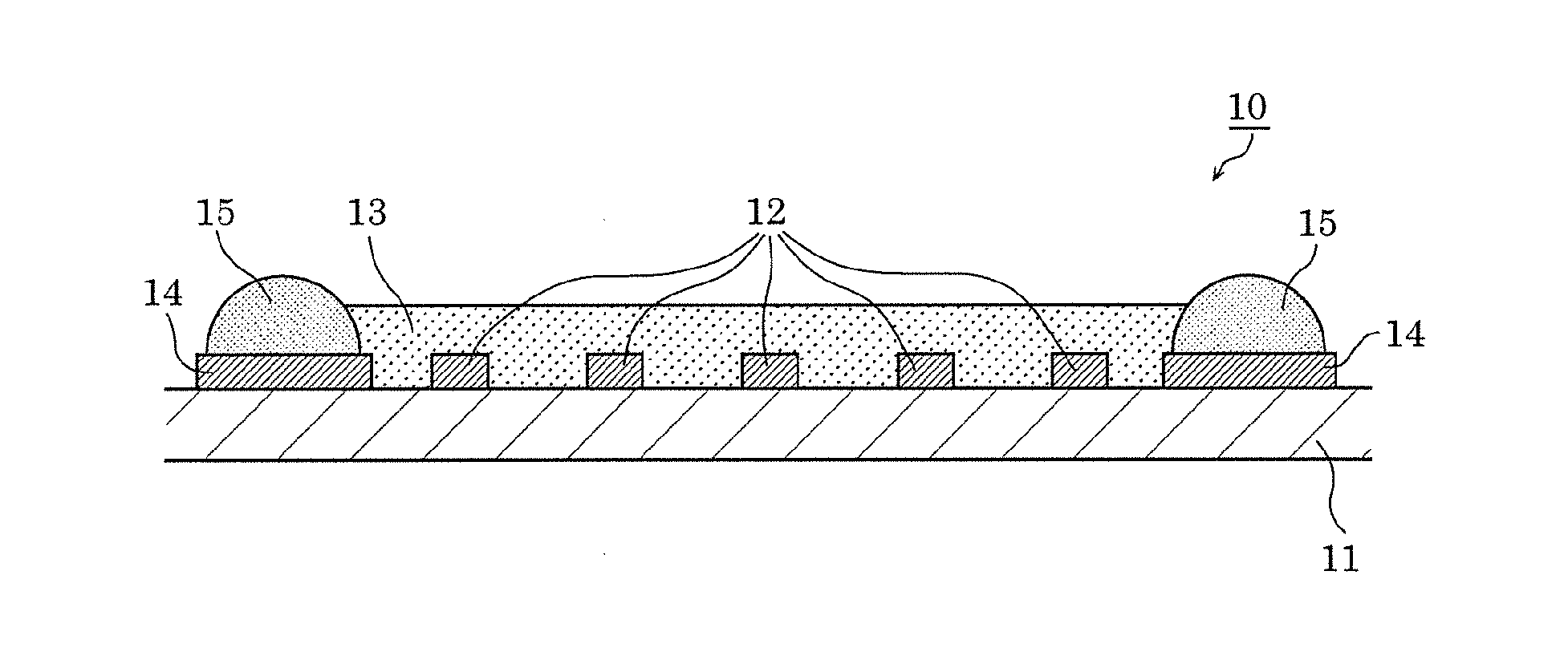
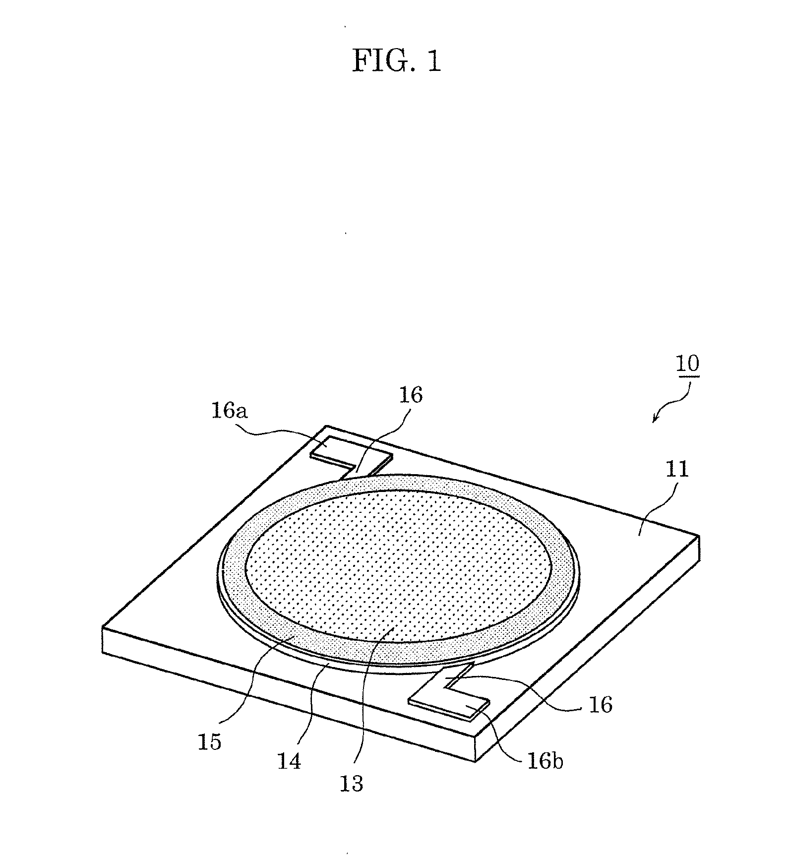
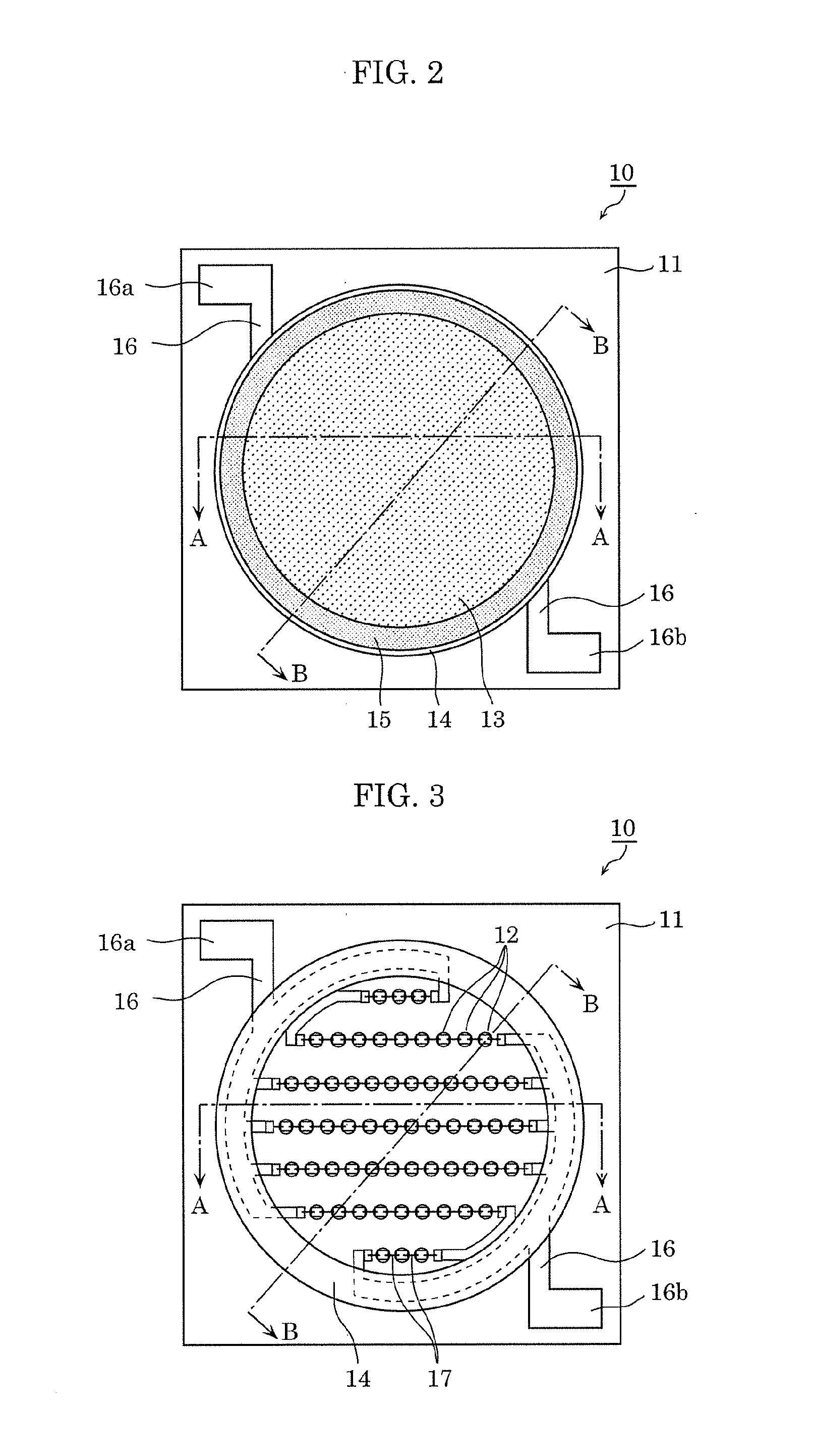
[0023]First, a configuration of a light emitting apparatus according to Embodiment 1 is described, with reference to the accompanying drawings. FIG. 1 is an external perspective view of the light emitting apparatus according to Embodiment 1. FIG. 2 is a plan view of the light emitting apparatus according to Embodiment 1. FIG. 3 is a plan view showing the internal structure of the light emitting apparatus according to Embodiment 1. FIG. 4 is a cross-sectional view of the light emitting apparatus, taken along A-A in FIG. 2. FIG. 5 is a cross-sectional view of the light emitting apparatus, taken along B-B in FIG. 2. It should be noted that FIG. 3 is a plan view of the light emitting apparatus from which sealing member 13 and dam material 15 in FIG. 2 are excluded, showing the internal structure, such as arrangement of LED chips 12 and an interconnection pattern.

[0024]As shown in FIGS. 1 through 5 light emitting apparatus 10 according to Embodime...

embodiment 2

[0069]Next, lighting apparatus 200 according to Embodiment 2 is to be described, with reference to FIGS. 8 and 9. FIG. 8 is a sectional view of lighting apparatus 200 according to Embodiment 2. FIG. 9 is an external perspective view of lighting apparatus 200 and its peripheral components according to Embodiment 2.

[0070]As shown in FIGS. 8 and 9, lighting apparatus 200 according to Embodiment 2 is, for example, a built-in lighting apparatus, such as a downlight, which is recessed into the ceiling in a house, for example, and emits light in a down direction (to a corridor, a wall, etc.).

[0071]Lighting apparatus 200 includes light emitting apparatus 10. Lighting apparatus 200 further includes a body having a substantially-closed-end cylindrical shape, configured of coupling base 210 and frame member 220 being coupled with each other, and reflector 230, and translucent panel 240 which are disposed on the body.

[0072]Base 210 is a mounting base on which light emitting apparatus 10 is moun...


PUM


Abstract

Light emitting apparatus including: substrate; LED chips on substrate; sealing member sealing LED chips; buffer layer on substrate; and dam material on the top surface of buffer layer, for holding back sealing member, wherein the adhesive strength of buffer layer to substrate and the adhesive strength of dam material to buffer layer are higher than the adhesive strength of dam material to substrate.

Description

CROSS REFERENCE TO RELATED APPLICATION[0001]This application claims the benefit of priority of Japanese Patent Application Number 2014-186265, filed Sep. 12, 2014, the entire content of which is hereby incorporated by reference.BACKGROUND OF THE INVENTION[0002]1. Field of the Invention[0003]The present disclosure relates to a light emitting apparatus in which light emitting elements are mounted on a substrate, and a lighting apparatus using the light emitting apparatus.[0004]2. Description of the Related Art[0005]A semiconductor light emitting element, such as a light emitting diode (LED), is widely utilized as a highly efficient, space-saving light source in various lighting apparatuses for lighting applications, display applications, etc.[0006]A light emitting apparatus (a light emitting module) in which a plurality of LEDs mounted on a substrate are enclosed around a light reflecting resin (hereinafter, also referred to as a dam material) is also known (see Japanese Unexamined Pa...

Claims


Application Information

Patent Timeline
IPC IPC(8): H01L33/54H01L33/60
CPCH01L33/60H01L33/54H01L2924/181H01L25/0753H01L2924/00012
Inventor ISHIMORI, ATSUYOSHIOGATA, TOSHIFUMIABE, MASUMI
Owner PANASONIC INTELLECTUAL PROPERTY MANAGEMENT CO LTD
Why Eureka
Try Eureka