
Thermal barrier coating member, method for producing the same, thermal barrier coating material, gas turbine, and sintered body

a technology of thermal barrier coating and thermal barrier coating, which is applied in the direction of vacuum evaporation coating, non-positive displacement fluid engine, liquid fuel engine components, etc., can solve the problems of insufficient durability of ysz crystals against large thermal, inability to endure such a high temperature, and inability to meet the requirements of high temperature resistance, etc., to achieve excellent thermal barrier properties, reduce thermal conductivity, and reduce the effect of thermal conductivity

Active Publication Date: 2013-11-19
MITSUBISHI POWER LTD
View PDF45 Cites 9 Cited by
  • Summary
  • Abstract
  • Description
  • Claims
  • Application Information

AI Technical Summary

Benefits of technology

The present invention is about a new material called a thermal barrier coating that can protect against high temperatures and has high durability. This material can be applied to gas turbines to prevent them from getting damaged when used at high temperatures. Additionally, the invention provides a method for producing a high-quality thermal barrier coating. Overall, this patent aims to improve the performance and longevity of thermally-stressing components.

Problems solved by technology

However, although the material of the turbine blades is a refractory metal, it cannot endure such a high temperature.
When the gas turbine is operated at such a high temperature, there has been a concern in which a part of the ceramic layer is spalled away and its heat resistance is impaired during the operation of the gas turbine under severe operating conditions.
The above-described problem of the spalling of the ceramic layer composed of YSZ is caused by that the stability of YSZ crystals is insufficient in a high-temperature environment, and the YSZ crystals do not have sufficient durability against a large thermal stress.

Method used


Image

  • Thermal barrier coating member, method for producing the same, thermal barrier coating material, gas turbine, and sintered body
  • Thermal barrier coating member, method for producing the same, thermal barrier coating material, gas turbine, and sintered body
  • Thermal barrier coating member, method for producing the same, thermal barrier coating material, gas turbine, and sintered body

Examples


composition example 1

[0200]A composition having Sm2Zr2O7 doped with 10 mol % of MgO is referred to as Composition Example 1. To obtain this composition, Sm2O3 powder (Sm2O3 in fine powder of 99.9% purity, manufactured by Nippon Yttrium Co., Ltd.) and MgO powder (magnesium carbonate converted as MgO, manufactured by Tateho Chemical Industries Co., Ltd.) were used together with ZrO2 powder (ZrO2 in fine powder TZ-0, manufactured by Nippon Yttrium Co., Ltd.), as raw materials.

composition example 2

[0201]A composition having Sm2Zr2O7 doped with 20 mol % of MgO is referred to as Composition Example 2. To obtain this composition, the same raw materials as those of Composition Example 1 were used except for that the addition amount of MgO was changed.

composition example 3

[0202]A composition having Sm2Zr2O7 doped with 10 mol % of CaO is referred to as Composition Example 3. To obtain this composition, the same raw materials as those of Composition Example 1 were used except for that CaO was used instead of MgO, wherein a calcium carbonate reagent manufactured by Wako Pure Chemical Industries, Ltd. was converted as CaO and used as the raw material of CaO.


PUM

PropertyMeasurementUnit
porosityaaaaaaaaaa
porosityaaaaaaaaaa
temperatureaaaaaaaaaa

Abstract

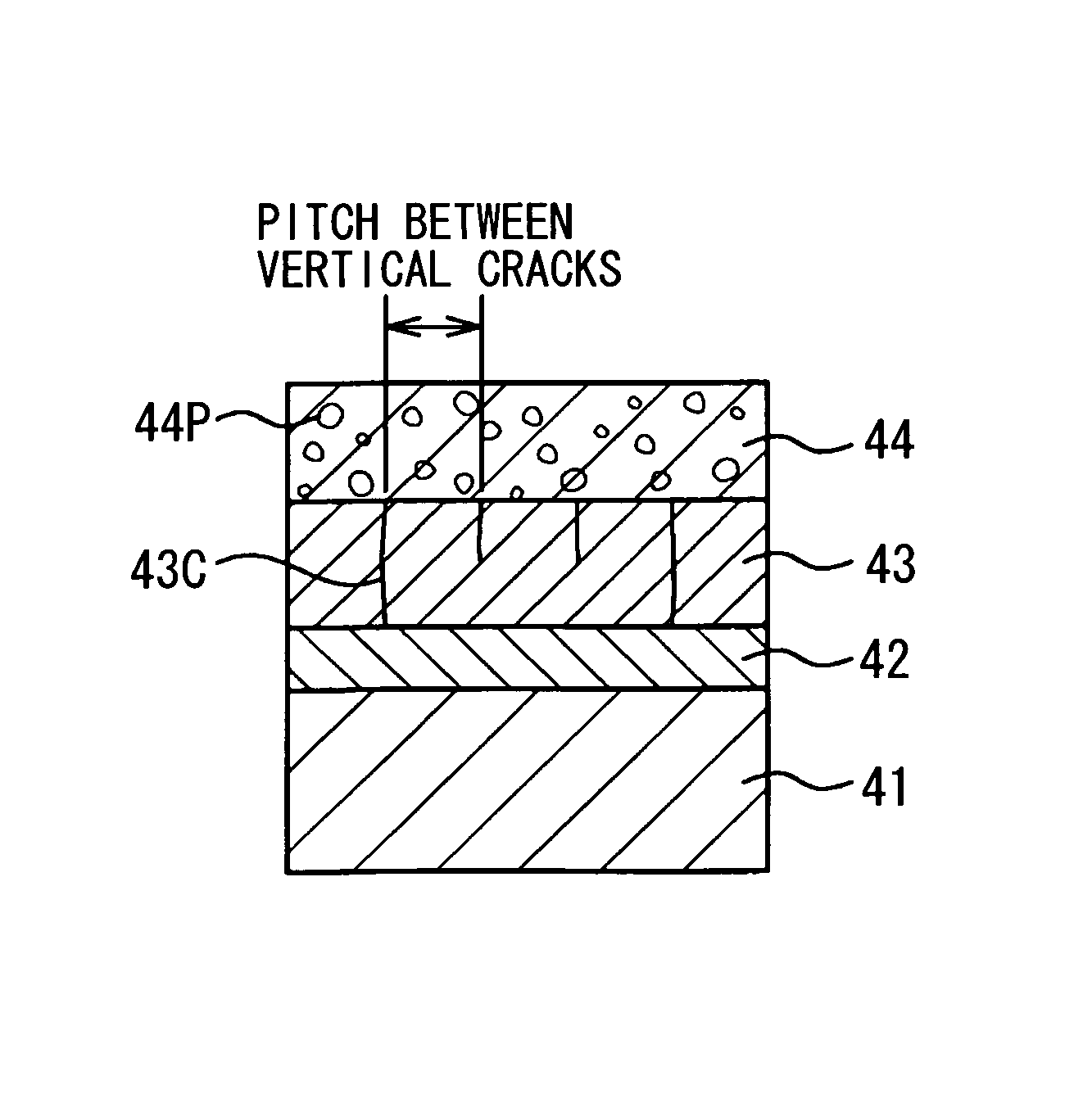
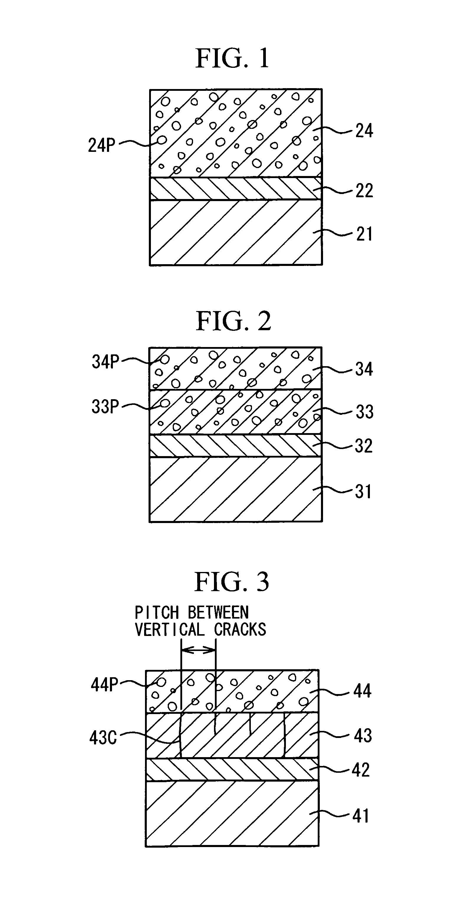
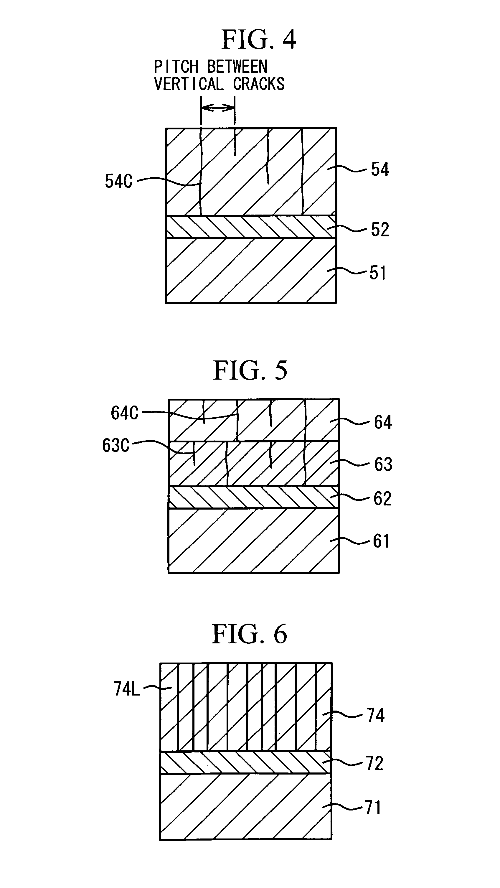
There are provided a thermal barrier coating material and a thermal barrier coating member that can suppress spalling when used at a high temperature and have a high thermal barrier effect, a method for producing the same, a turbine member coated with a thermal barrier coating, and a gas turbine. The thermal barrier coating member comprises a heat resistant substrate, a bond coat layer formed thereon, and a ceramic layer formed further thereon, wherein the ceramic layer comprises an oxide which consists of an oxide represented by the general formula A2Zr2O7 doped with a predetermined amount of CaO or MgO and has 10 volume % or more of a pyrochlore type crystal structure, where A represents any of La, Nd, Sm, Gd, and Dy.

Description

TECHNICAL FIELD[0001]The present invention relates to a thermal barrier coating material, a thermal barrier coating member, a gas turbine, and a sintered body which have excellent durability, and the production of the thermal barrier coating member, particularly to the structure of a ceramic layer used as a top coat of the thermal barrier coating member.BACKGROUND ART[0002]In recent years, the elevation of the thermal efficiency of thermal power generation has been examined as one of energy saving measures. In order to improve the power generation efficiency of a generator gas turbine, the elevation of the gas inlet temperature is effective, and in some cases, the temperature is elevated to about 1500° C. In order to realize the temperature elevation in power generators in this way, a stationary blade, a moving blade, the wall material of a combustor, or the like which constitute the gas turbine are required to be constituted with heat resistant members. However, although the materi...

Claims


Application Information

Patent Timeline
Patent Type & Authority Patents(United States)
IPC IPC(8): B32B15/00C09D1/00B05D5/00B05D1/36C23C14/34
CPCC04B35/486C23C4/02C23C4/105C23C30/00F01D5/288F02K9/974C04B2235/3206C04B2235/3208C04B2235/3224C04B2235/3225C04B2235/3227C04B2235/3229C04B2235/441C04B2235/656C04B2235/76C04B2235/77C04B2235/787C04B2235/9607F05D2230/90C23C4/11Y10T428/24471Y10T428/31678Y10T428/24999Y02T50/60
Inventor NAMBA, KATSUMITORIGOE, TAIJIOKADA, IKUOMORI, KAZUTAKANAGANO, ICHIROKAWATA, YUTAKATAKAHASHI, KOJI
Owner MITSUBISHI POWER LTD
Learn More