Dual-polarized radiating patch antenna

a patch antenna and radiating technology, applied in the field of patch antennas, can solve the problems of polarization isolation below 25 db, differential reflectivity (zdr) is particularly vulnerable to changes in polarization basis, and the accuracy of measurements obtained is particularly vulnerable to dual-polarization features,

Active Publication Date: 2016-03-17
UNIV FOR ATMOSPHERIC RES
View PDF4 Cites 65 Cited by
  • Summary
  • Abstract
  • Description
  • Claims
  • Application Information

AI Technical Summary

Problems solved by technology

In phased array radars, the accuracy of measurements obtained are particularly vulnerable to the features of the dual-polarization.
For example, differential reflectivity (ZDR) is particularly vulnerable to changes in the polarization basis.
Polarization isolation below −25 dB is difficult to obtain using prior art dual-polarized...

Method used


Image

  • Dual-polarized radiating patch antenna
  • Dual-polarized radiating patch antenna
  • Dual-polarized radiating patch antenna

Examples


Embodiment Construction

[0033]FIGS. 1-7d and the following description depict specific examples to teach those skilled in the art how to make and use the best mode of the application. For the purpose of teaching inventive principles, some conventional aspects have been simplified or omitted. Those skilled in the art will appreciate variations from these examples that fall within the scope of the application. Those skilled in the art will appreciate that the features described below can be combined in various ways to form multiple variations of the application. As a result, the application is not limited to the specific examples described below, but only by the claims and their equivalents.

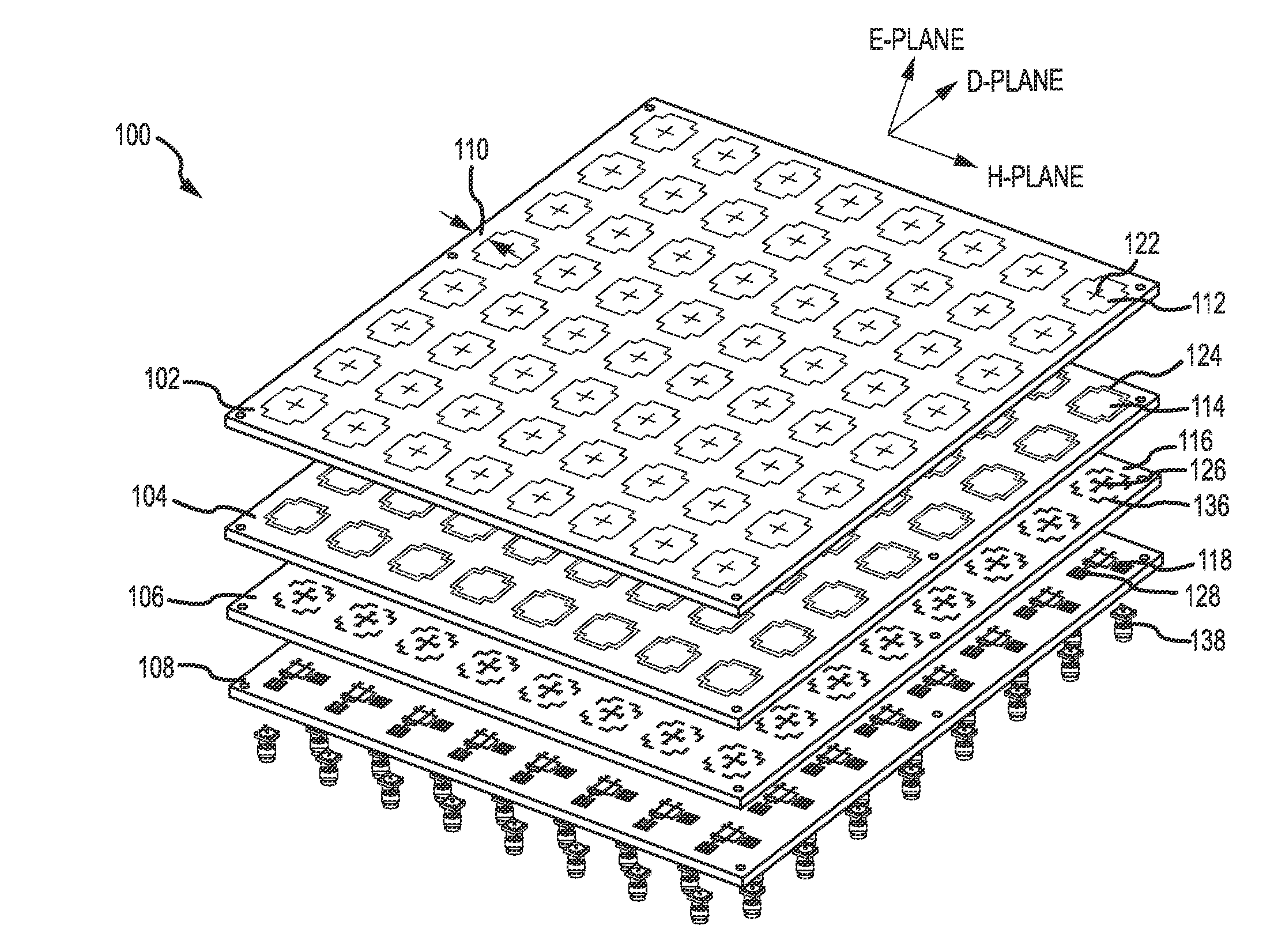
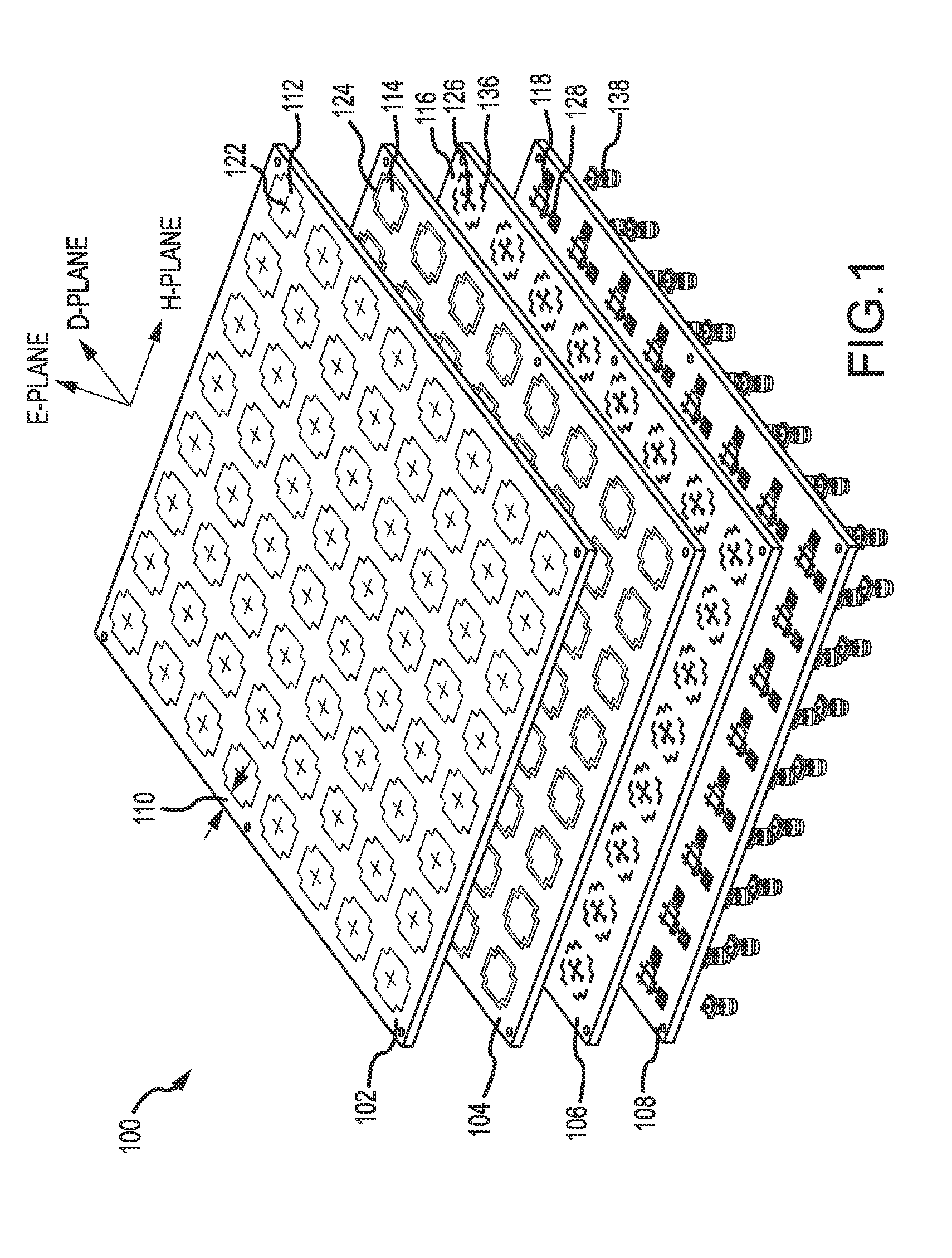
[0034]FIG. 1 depicts an exploded view of a dual-phased patch antenna array 100 in accordance with an embodiment of the application. In an example embodiment, patch antenna array 100 operates at a frequency of 5.4 GHz. This is not intended to be limiting, however, as the application contemplates patch antennas that operate...


PUM


Abstract

A dual-polarized patch antenna, an dual-polarized patch antenna array, and a method for forming the same are provided. The dual-polarized patch antenna comprises a radome, a horizontal feed and a vertical feed, a first cross-shaped patch, and a ground plane including a cross aperture. The dual-polarized patch antenna may include a cross patch and a cross aperture to increase the isolation in a cross-polarization between a horizontal polarized signal and a vertical polarized signal in a first principle plane and to decrease a mismatch in co-polarizations between the horizontal polarized signal and the vertical polarized signal in a second principle plane.

Description

CROSS-REFERENCE TO RELATED APPLICATION[0001]This application claims priority from U.S. Provisional Patent Application No. 62 / 004,332, filed May 29, 2014, entitled “Dual-polarized Radiating Patch Antenna,” the contents of which are incorporated herein by reference.GOVERNMENT LICENSE RIGHTS[0002]This invention was made with Government support under the National Science Foundation Directorate for Geosciences Division of Atmospheric and Geospace Sciences with Award Numbers M0904552 and M0856145. The Government has certain rights in this invention.TECHNICAL FIELD[0003]The present application relates to antennas, and more particularly, to an improved method and apparatus for a patch antenna.BACKGROUND OF THE APPLICATION[0004]Patch antennas, or microstrip antennas are widely used in the wireless, radar, automobile, military, and space industries. Patch antenna technology offers low-profile, low-cost features that are fundamental for the wireless and communication industries. Cell phones, G...

Claims


Application Information

Patent Timeline
IPC IPC(8): H01Q9/04H01Q1/42H01Q1/48H01Q21/26
CPCH01Q9/045H01Q21/26H01Q1/42H01Q1/48H01Q21/24H01Q21/065
Inventor CERRENO, JORGRE, LUIS, SALAZAR
Owner UNIV FOR ATMOSPHERIC RES
Why Eureka
Try Eureka