Current converter apparatus having a multi-phase current converter

a current converter and multi-phase technology, applied in the direction of electrical apparatus construction details, electrical apparatus casings/cabinets/drawers, printed circuit board receptacles, etc., can solve the problems of contaminating the current converter cabinet, having to replace the converter module or its busbar, and cleaning the current converter cabinet in a time-consuming and costly manner. , to achieve the effect of preventing contamination of the current converter cabinet and facilitating electrical conta

Active Publication Date: 2016-03-17
SIEMENS AG
View PDF19 Cites 7 Cited by
  • Summary
  • Abstract
  • Description
  • Claims
  • Application Information

AI Technical Summary

Benefits of technology

[0016]According to another advantageous feature of the present invention, a rectifier can be arranged in the current-converter cabinet and connected electrically to the module rows, or a feed-return inverter can be arranged in the current-converter cabinet and connected electrically to the current converter. The feed-return inverter is also referred to as an Active Front End (AFE). The mains frequency of a supply network connected to the current converter can advantageously be adjusted in these embodiments of the current converter module by the rectifier or the feed-return inverter. A feed-return inverter also advantageously enables a return of energy into the supply network that is provided by a load operated using the current converter, e.g. a motor.
[0017]According to another advantageous feature of the present invention, a braking chopper can be arranged in the current-converter cabinet and co

Problems solved by technology

If a current converter module is damaged, in the event of a short circuit in a current converter module, for instance, other current converter modules and even the entire interior of the current converter cabine

Method used


Image

  • Current converter apparatus having a multi-phase current converter
  • Current converter apparatus having a multi-phase current converter
  • Current converter apparatus having a multi-phase current converter

Examples


Embodiment Construction

[0027]Throughout all the figures, same or corresponding elements may generally be indicated by same reference numerals. These depicted embodiments are to be understood as illustrative of the invention and not as limiting in any way. It should also be understood that the figures are not necessarily to scale and that the embodiments are sometimes illustrated by graphic symbols, phantom lines, diagrammatic representations and fragmentary views. In certain instances, details which are not necessary for an understanding of the present invention or which render other details difficult to perceive may have been omitted.

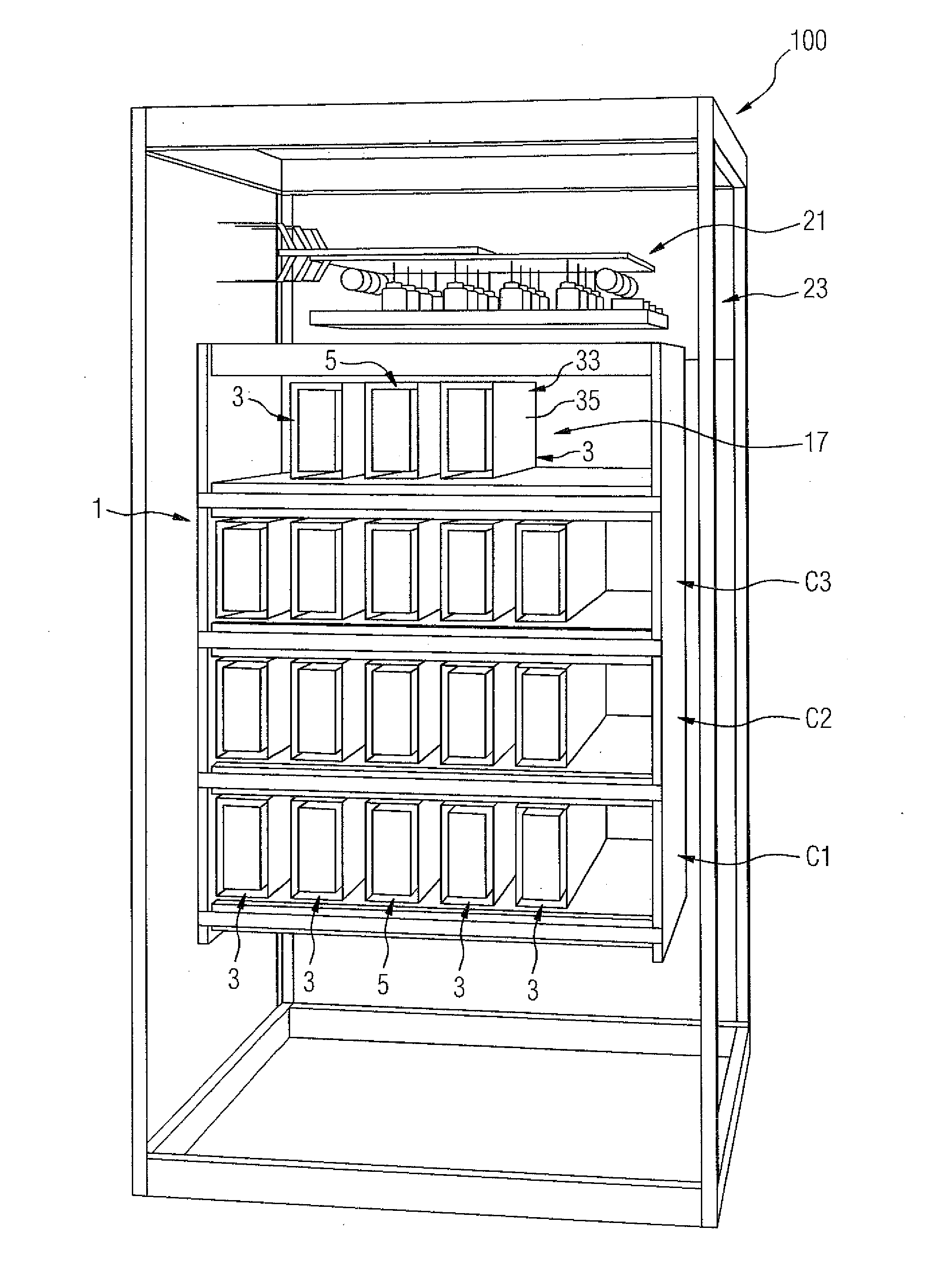
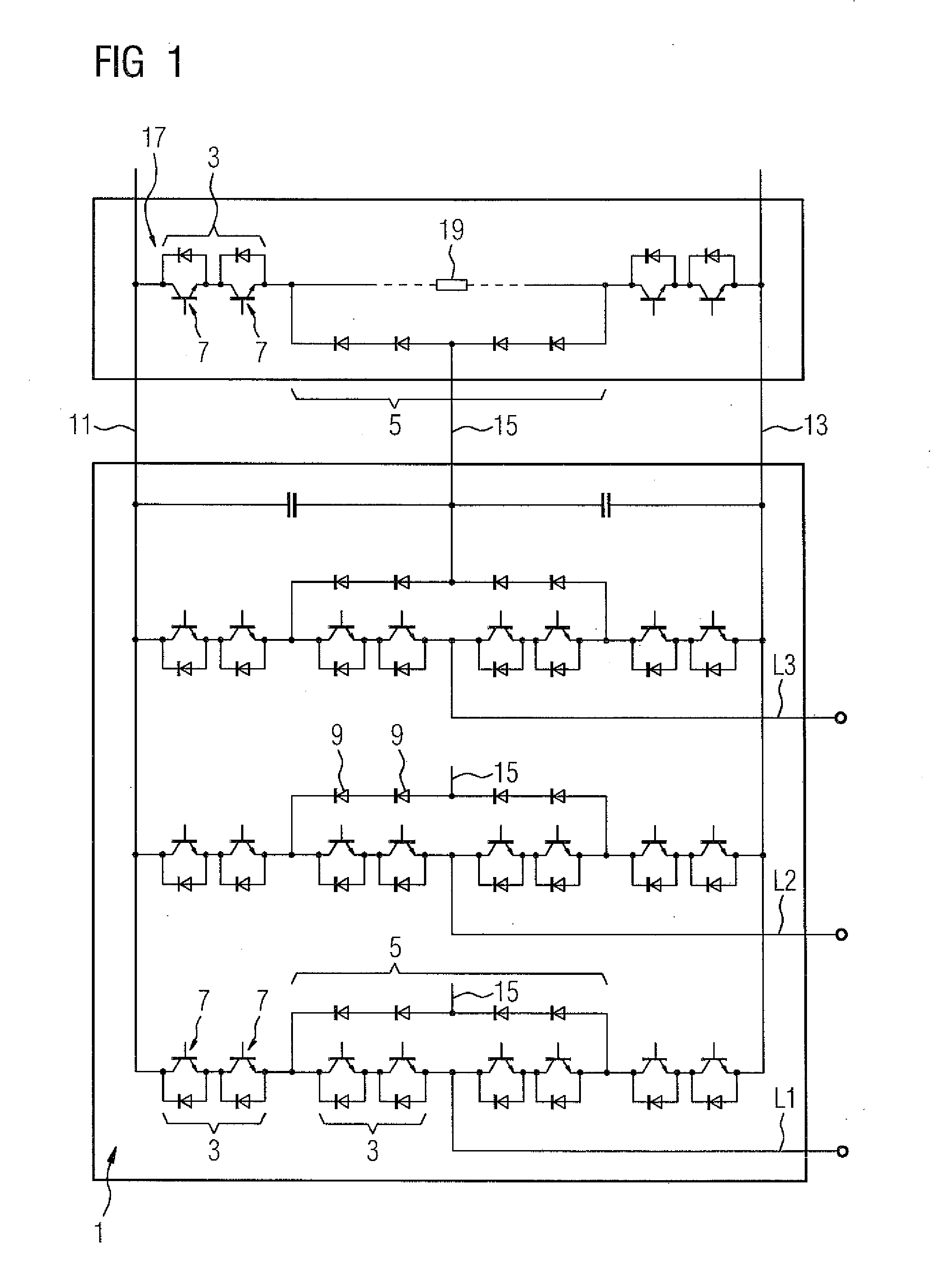
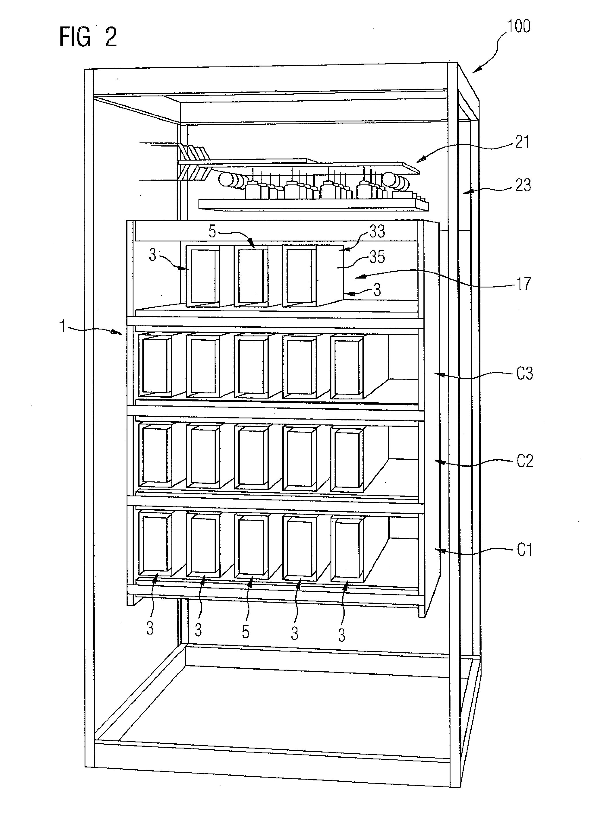
[0028]Turning now to the drawing, and in particular to FIG. 1, there is shown a circuit diagram of a three-phase current converter 1. The current converter 1 has what is called a three-point inverter “in NPC topology” (NPC=Neutral Point Clamped). This three-phase current converter 1 has four first current-converter modules 3, a second-current converter module 5 and an exteri...


PUM


Abstract

A current converter apparatus includes a multi-phase current converter having current-converter modules for each phase that are electrically connected to one another and arranged in a current-converter cabinet. Each current-converter module has at least one semiconductor component arranged on a heat sink and includes just two semiconductor components connected to each other and connected to be controlled by a control component. The current-converter modules in the current-converter cabinet are arranged so that the current-converter modules of each current-converter phase form a horizontal row of modules arranged one beside the other and the rows are arranged vertically one above the other.

Description

CROSS-REFERENCES TO RELATED APPLICATIONS[0001]This application claims the priority of European Patent Application, Serial No. 14184362.3, filed Sep. 11, 2014, pursuant to 35 U.S.C. 119(a)-(d), the content of which is incorporated herein by reference in its entirety as if fully set forth herein.BACKGROUND OF THE INVENTION[0002]The invention relates to a current converter apparatus having a multi-phase current converter including a number of current converter modules electrically connected to one another for each current converter phase.[0003]The following discussion of related art is provided to assist the reader in understanding the advantages of the invention, and is not to be construed as an admission that this related art is prior art to this invention.[0004]Modular current converters are frequently installed in current-converter cabinets. If a current converter module is damaged, in the event of a short circuit in a current converter module, for instance, other current converter...

Claims


Application Information

Patent Timeline
IPC IPC(8): H05K5/00
CPCH05K5/0013H05K7/14325H05K7/20H02M7/1555H05K7/20927H05K7/20672H05K7/1432
Inventor HETZEL, BRIGITTEHILLER, MARCPFAUSER, ANTONPOPP, GUDRUNSCHICKERT, ELFRIEDE
Owner SIEMENS AG
Why Eureka
Try Eureka