
Head and automated mechanized method with vision

Active Publication Date: 2016-03-24
LOXIN 2002
View PDF11 Cites 22 Cited by
  • Summary
  • Abstract
  • Description
  • Claims
  • Application Information

AI Technical Summary

Benefits of technology

The patent describes an automated machining head with vision that improves the accuracy of a robot used for machining processes. The main advantage is that it can provide higher accuracy than existing equipment. The head also compensates for off-centering and loss of perpendicularity caused by pressure foot, which is common in conventional heads. The vision system allows for real-time correction of robot positioning points, ensuring repeatability and reducing accuracy dependent on robot accuracy. The solution presented is cost-effective, efficient, and simple, and can contribute to innovation in manufacturing techniques and process improvements, reducing costs.

Problems solved by technology

They are versatile, relatively inexpensive devices, but their main drawback is their lack of stiffness and consequently their lack of accuracy, which can lead to errors of more than 2 mm, making them unsuitable for applications in which requirements, in terms of accuracy, are greater by several orders of magnitude, such as for instance, machining, drilling and riveting applications in the aeronautical industry, requiring accuracies of hundredths or thousandths of mm.
These degrees of accuracy can be achieved by high-precision equipment or parallel kinematic machines, but they have the drawback of their high cost due to the precision technology required to manufacture them and the control technologies required.
When using anthropomorphic robots there are applications that can improve their accuracy by means of external measuring systems in which, for example, a laser tracker detects the position of the robot head in space and sends out the corresponding orders to correct it, however, in addition to the high cost of this equipment, it has the major drawback that the field of vision between the robot and the external measuring equipment must always be clear, which represents a significant disadvantage and, in most applications, is not possible.
There have been some attempts to improve the intrinsic accuracy of anthropomorphic robots, usually by modifying standard robots in order to add high-accuracy secondary encoders on the output shafts of the reducers that move the robot arm axes and normally replacing, in some cases at the same time, the robot controller with a CNC, thereby achieving a partial increase in its stiffness and improving accuracy but with the drawback of its high cost, eliminating one of the greatest advantages of these robots, as well as resulting in problems with maintenance and adjustments and with spare parts since these are not longer standard or serial robots that form part of the manufacturer's catalogue and hence customers or end users are additionally dependent on the company that modifies the robots.
There are also known applications of video cameras on robots, such as those disclosed in patents WO03064116A2, US2010286827A1, US2003144765A1, ES2142239_A1 , ES2036909_A1 and CN101205662, however, as in the previous case, their purpose is to provide a good view of the work area during the programming of the robot, without achieving increased accuracy in an automatic way.
In addition, robots equipped with two cameras are also known, as described in patents CN101726296 and WO2006019970A2, but they do not help to improve the accuracy of the robot, but rather are only for recognising shapes or objects.
Procedures are also known for improving the intrinsic precision of anthropomorphic robots without vision equipment, based purely on mechanical elements, such as that disclosed in patent US2009018697, in which a mechanical system is used to measure the deviations of the robot when additional forces are applied, but which present the problem that when mechanical slippage occurs between the workpiece and the measuring nozzle, it is no longer possible to return to the target point.
As previously mentioned, on the one hand, robots are not particularly precise devices in terms of their positioning and orientation accuracy and, on the other, if additional forces are applied once the robot has reached a certain position, this will alter both its orientation and position.

Method used


Image

  • Head and automated mechanized method with vision
  • Head and automated mechanized method with vision
  • Head and automated mechanized method with vision

Examples


Embodiment Construction

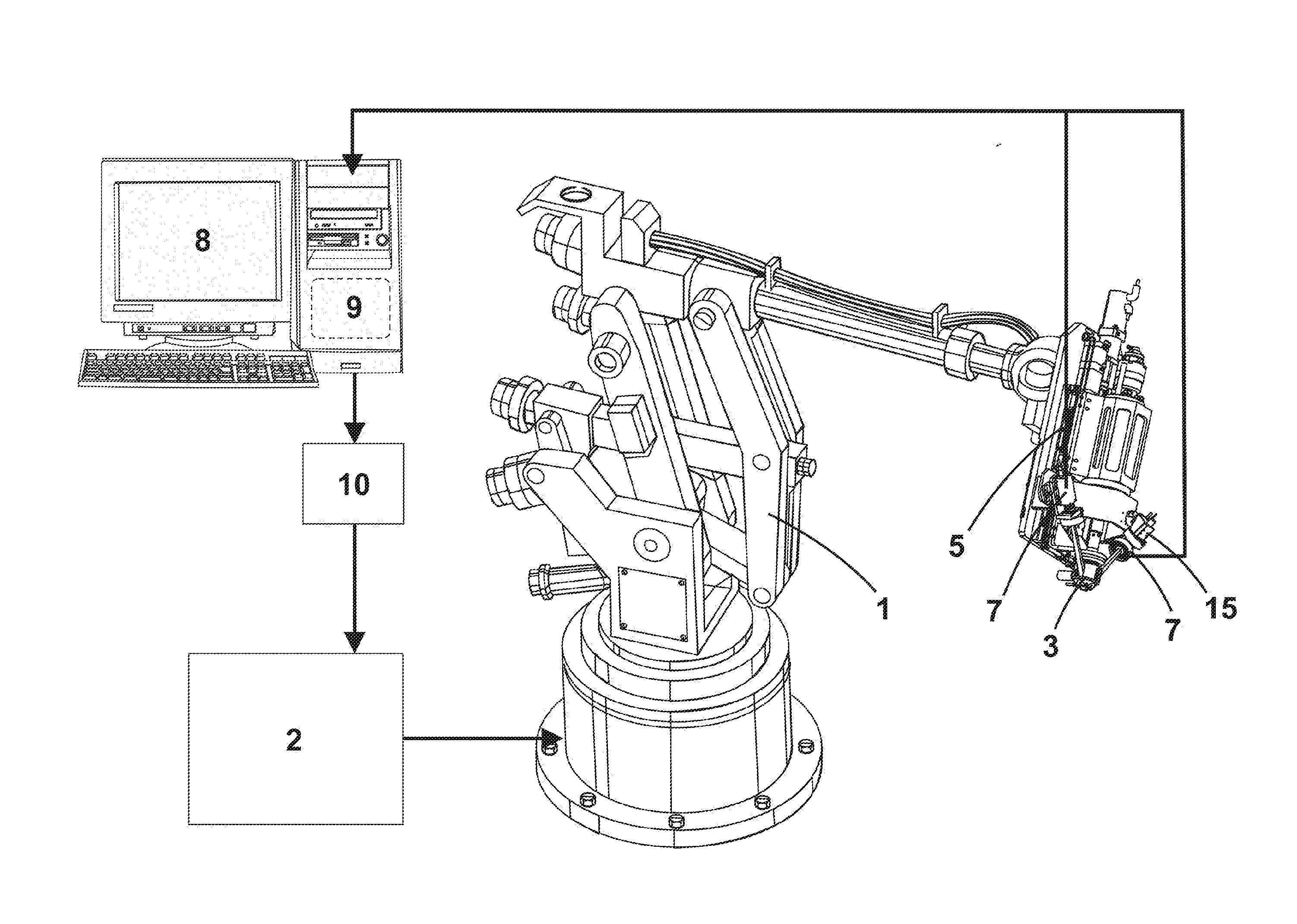
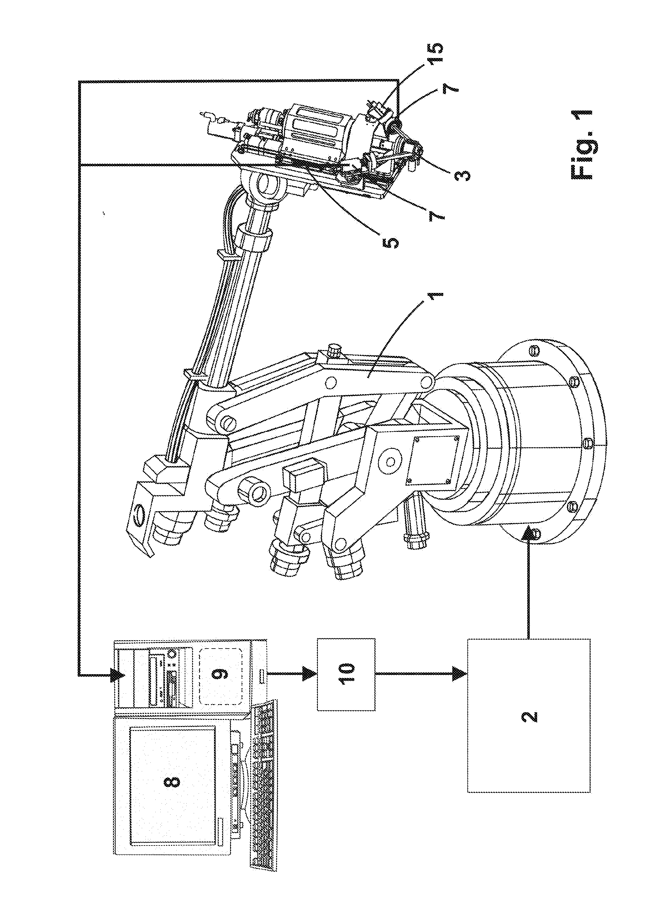
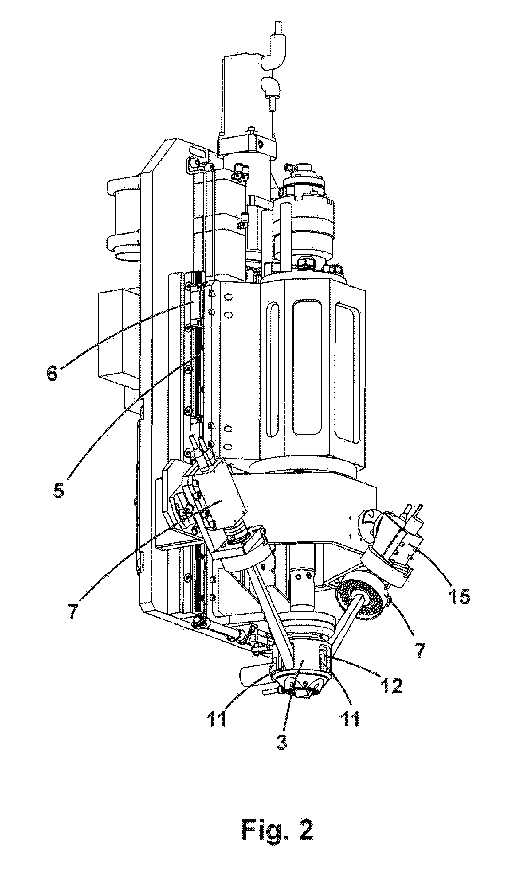
[0066]The automated machining head with vision and procedure that is the subject matter of this invention is associated with a robot arm (1) to perform various machining tasks, especially drilling and riveting, controlled by a robot controller module (2), and basically comprises, as can be seen in the drawing attached, a pressure foot (3), encasing the machining tool (4), associated with a vertical movement device (5) provided with mechanical locking (6), 3-D type vision equipment provided with at least two video cameras (7), connected to a computer (8) provided with specific software (9), and a communications module (10). The communications module (10) may be either a specific hardware device or a part of the specific software (9).

[0067]It is envisaged that the vision equipment may optionally comprise a laser device (15) which projects a cross-shaped beam inside the pressure foot (3). The projection of this cross onto the workpiece to be drilled is used by the artificial vision cam...


PUM

PropertyMeasurementUnit
Pressureaaaaaaaaaa
Distanceaaaaaaaaaa

Abstract

An automated machining head with vision and procedure includes a pressure foot provided with side windows with the capacity to open and close, encasing the machining tool, associated with a vertical movement device provided with mechanical locking, vision equipment connected to a computer and a communications module. The main advantage is endowing an anthropomorphic robot, originally designed for the car industry and with relatively low accuracy, with a notably higher machining accuracy, equivalent to equipment of a much greater accuracy or to parallel kinematic-type robots, also compensating, in real-time and in a continuous manner, for off-centring and loss of perpendicularity by the pressure foot, which are common in conventional heads and are a source of errors and inaccuracy.

Description

[0001]This description relates, as its title indicates, to an automated machining head with vision of the type used industrially associated with anthropomorphic robot arms to perform various machining tasks, in particular drilling and riveting, controlled by a robot controller module and comprising a pressure foot, provided with side windows capable of opening and closing, encasing the machining tool, associated with an axial movement device provided with mechanical locking, vision equipment connected to a computer and a communications module between the latter and the robot controller module that allows the vision equipment to interact with the robot controller, all of this with a characteristic operating procedure.FIELD OF THE INVENTION[0002]The invention relates mainly but not exclusively to the field of machining heads, in particular for drilling and riveting, associated with anthropomorphic robot arms.THE PRIOR ART[0003]Anthropomorphic robots are currently known and widely used...

Claims


Application Information

Patent Timeline
IPC IPC(8): B25J11/00B25J9/16B25J19/02G06T1/00
CPCB25J11/005B25J9/1697B25J19/02Y10S901/10B25J9/1692G06T1/0014B25J19/022B25J19/023B25J11/007B21J15/142B21J15/14B25J19/021
Inventor ANDUCAS, AREGALL, JORDIGANCHEGUI, ITURRIA, CARLOSGALARZA, CAMBRA, JOSE, JAVIER
Owner LOXIN 2002
Learn More