Deployable flexible flood mitigation wall

Active Publication Date: 2016-03-24
ILC DOVER LP
View PDF10 Cites 9 Cited by
  • Summary
  • Abstract
  • Description
  • Claims
  • Application Information

AI Technical Summary

Benefits of technology

[0012]The trench and wall assembly can be designed to form a perimeter around a structure of any shape, and can include concave and convex features. It can be formed on slopes, across curbs, or can be placed above ground in the form of a bench. The trench, usually formed in concrete to react the loads from water impinging on the deployable wall, can be any shape or size to accommodate short or tall walls. If the reaction loads on the trench from the post loads become prohibitive on the trench then a deployable buttress can be added to the posts. The buttress will direct loads to the landing point of the buttress and greatly reduce the loads induced on the trench. The spacing of the posts can also be altered to increase the strength of the wall when spaced close together, or reduce the cost of the wall by spreading them apart.
[0013]The flexible wall assembly can prevent impingement of the wall, and thus force of the water, on the structure it is protecting (glass windows, etc.). This can be done by positioning the trench away from the structure, or by angling the posts away from the structure i

Problems solved by technology

Most deployable systems cannot seal effectively to the ground because of surface roughness, cracks, and undulations in the surface, and therefore leak

Method used


Image

  • Deployable flexible flood mitigation wall
  • Deployable flexible flood mitigation wall
  • Deployable flexible flood mitigation wall

Examples


Embodiment Construction

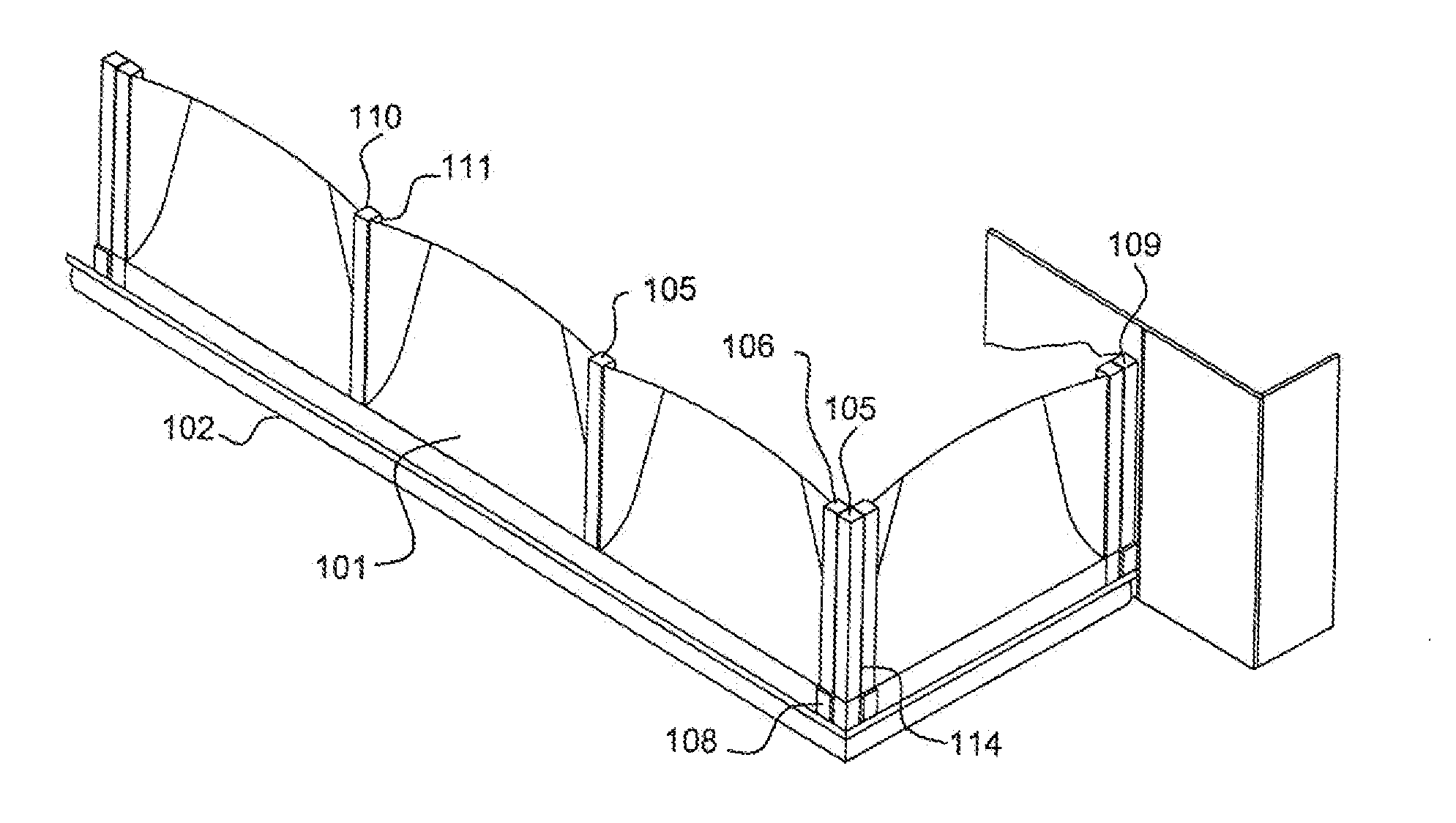
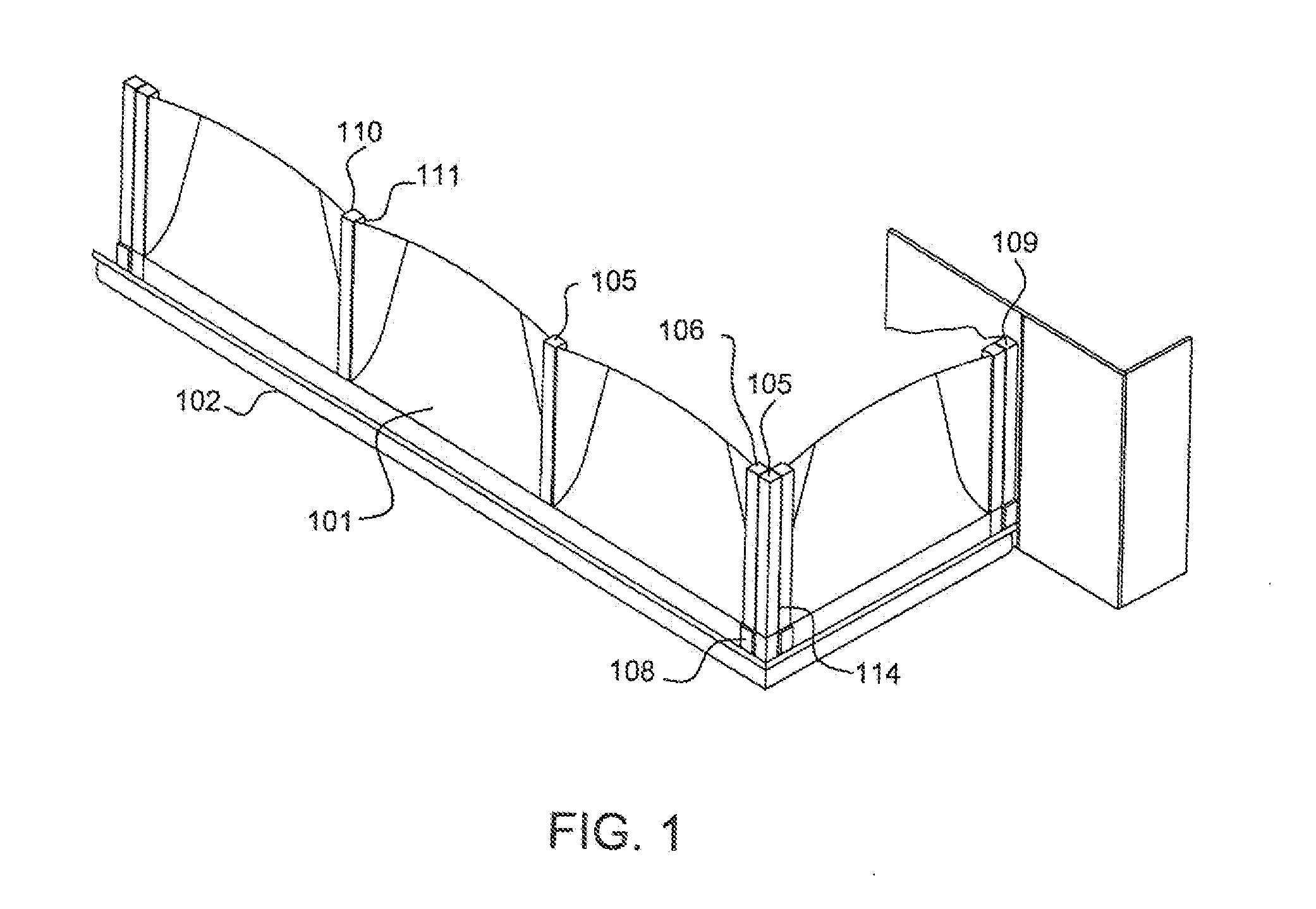
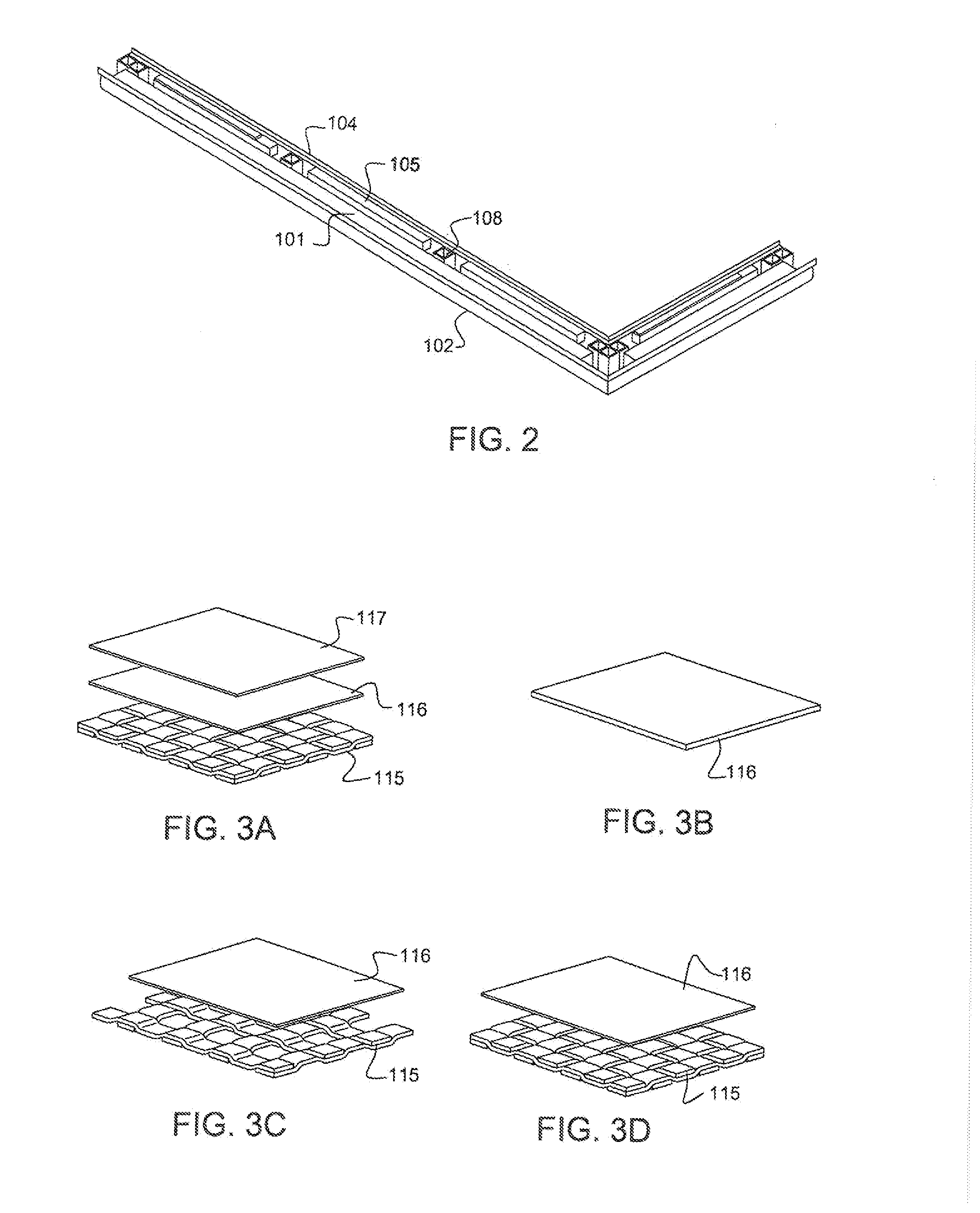
[0024]FIG. 1 illustrates a perspective view of a Deployable Flexible Flood Wall with the wall in the deployed position 100 according to an embodiment of the present invention. FIG. 2 illustrates the Deployable Flexible Flood Wall 100 in its stowed condition with the cover removed. FIGS. 3 through 8 respectively illustrate detailed views of critical features of the Deployable Flexible Flood Wall 100. The Deployable Flexible Flood Wall is also referred to as the Flex-Wall.

[0025]As shown in FIGS. 1, 2, 5, 6 and 7, the Deployable Flexible Flood Wall 100 is comprised of a textile & membrane flexible wall 101, a trench 102, a sealing clamp 103, a mounting plate 104, a post 105, a clamping post 106, a buttress 107, a receiver 108, a wall seal 109, a tether 110, an anchor 111, and cover 112.

[0026]The flexible wall 101 is folded and stored in the trench 102 and can be moved from a stowed to a deployed position and visa-versa. The flexible wall 101 is attached to the mounting plate 104 with t...


PUM


Abstract

A novel design and construction method for the creation of a deployable flexible flood mitigation wall manufactured from textile and membrane materials. The flexible flood mitigation wall system comprises a textile/membrane wall and support posts configured to be movable between a stowed position and a deployed position and wherein, in the deployed position, the wall forms a leak-free barrier against flood water or other fluids. A series of posts that are manually deployed is used to support the fabric wall when hydrostatically challenged, and transfer loads to the ground. The wall is stored at the point of use in a surface box or trench box and keeps the loading from the flood water off the building, structure or equipment being protected. The flexible flood mitigation wall can be configured for use in many applications including entire buildings, building entrances, transit system passages such as ventilation shafts or elevator shafts, windows, stairwells, and other openings that can be threatened by flooding. It can be continuous such that it surrounds structures such as buildings and power substations, homes, or segmented, such that it can be used to seal openings of all kinds including human or vehicle doorways. It can be tailored to fit any opening and water height.

Description

FIELD OF THE INVENTION[0001]The present invention relates to a Flexible Flood Mitigation Device system that is scalable in size, shape, and orientation to a wide variety of applications. The invention can be used to seal part or all of an opening from flood water or other fluid threats, or completely surround a building or structure for protection.BACKGROUND OF THE INVENTION[0002]Flooding events can be precipitated by natural and manmade inputs. These events can be particularly challenging for buildings and infrastructure located at or near a body of water. Transportation systems or buildings in these areas that are below the normal waterline are particularly vulnerable. Severe storms with high tidal surges or flash floods, rising sea levels, and seismic activity are some of the challenges posed by nature. Accidents, terrorism, and mechanical failures are manmade threats that can cause flooding, or magnify flooding from natural events.[0003]Many subway and vehicular tunnels that ope...

Claims


Application Information

Patent Timeline
IPC IPC(8): E02B3/04
CPCE02B3/04E06B9/0692E06B2009/007E02B3/102E02B3/106
Inventor CADOGAN, DAVID, PHILLIPHINKLE, JONATHAN, MICHAELSANDY, CHARLES, RALPHKNOLL, JR., CARL, FRANK
Owner ILC DOVER LP
Why Eureka
Try Eureka