
Transmitter and method of processing transmission signals

a transmission signal and transmitter technology, applied in the field of transmitters, can solve the problems of complex construction, inability to support, and inability to support ca technology, which should bind multiple bands, and achieve the effect of simplifying the structur

Active Publication Date: 2016-03-24
SAMSUNG ELECTRONICS CO LTD
View PDF5 Cites 1 Cited by
  • Summary
  • Abstract
  • Description
  • Claims
  • Application Information

AI Technical Summary

Benefits of technology

The patent aims to simplify the structure of a transmitter by reducing the number of components in the power amplifier. This is achieved by separating the uplink carrier aggregation or MMMB power amplifier into a low-band and a high-band, which can be used to support DSDA. This simplification helps to improve the overall performance and efficiency of the transmitter.

Problems solved by technology

Therefore, the CA technology, which should bind multiple bands, cannot be supported.
However, to use three or more PAMs requires increased power consumption by the transmitter and more connections for transferring signals, such that the transmitter is less efficient and its construction is more complicated.

Method used


Image

  • Transmitter and method of processing transmission signals
  • Transmitter and method of processing transmission signals
  • Transmitter and method of processing transmission signals

Examples


Embodiment Construction

[0030]Hereinafter, various embodiments of the present disclosure will be described in detail with reference to the accompanying drawings. Further, in the following description of the present disclosure, detailed descriptions of known functions and configurations incorporated herein will be omitted when they may make the subject matter of the present disclosure unclear. The terms which will be described below are terms defined in consideration of the functions in the present disclosure, and may be different according to users, intentions of the users, or customs. Therefore, the definitions of the terms should be determined based on the contents throughout the specification.

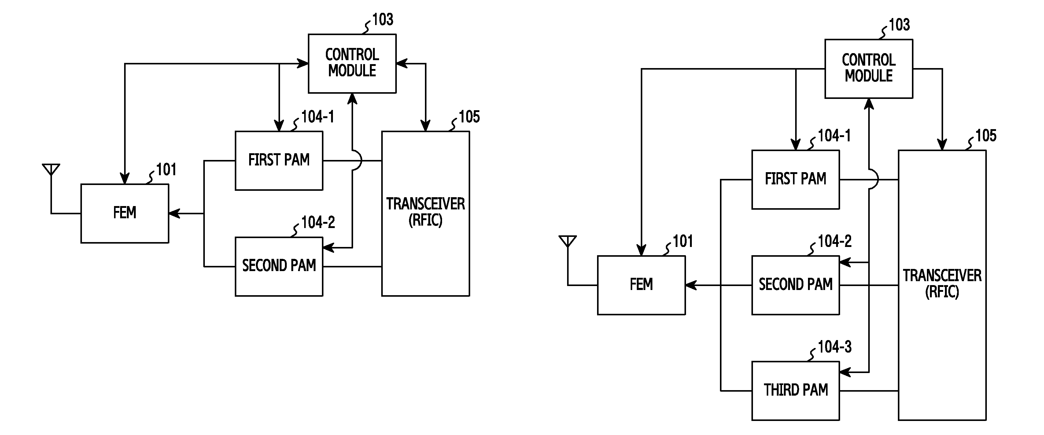
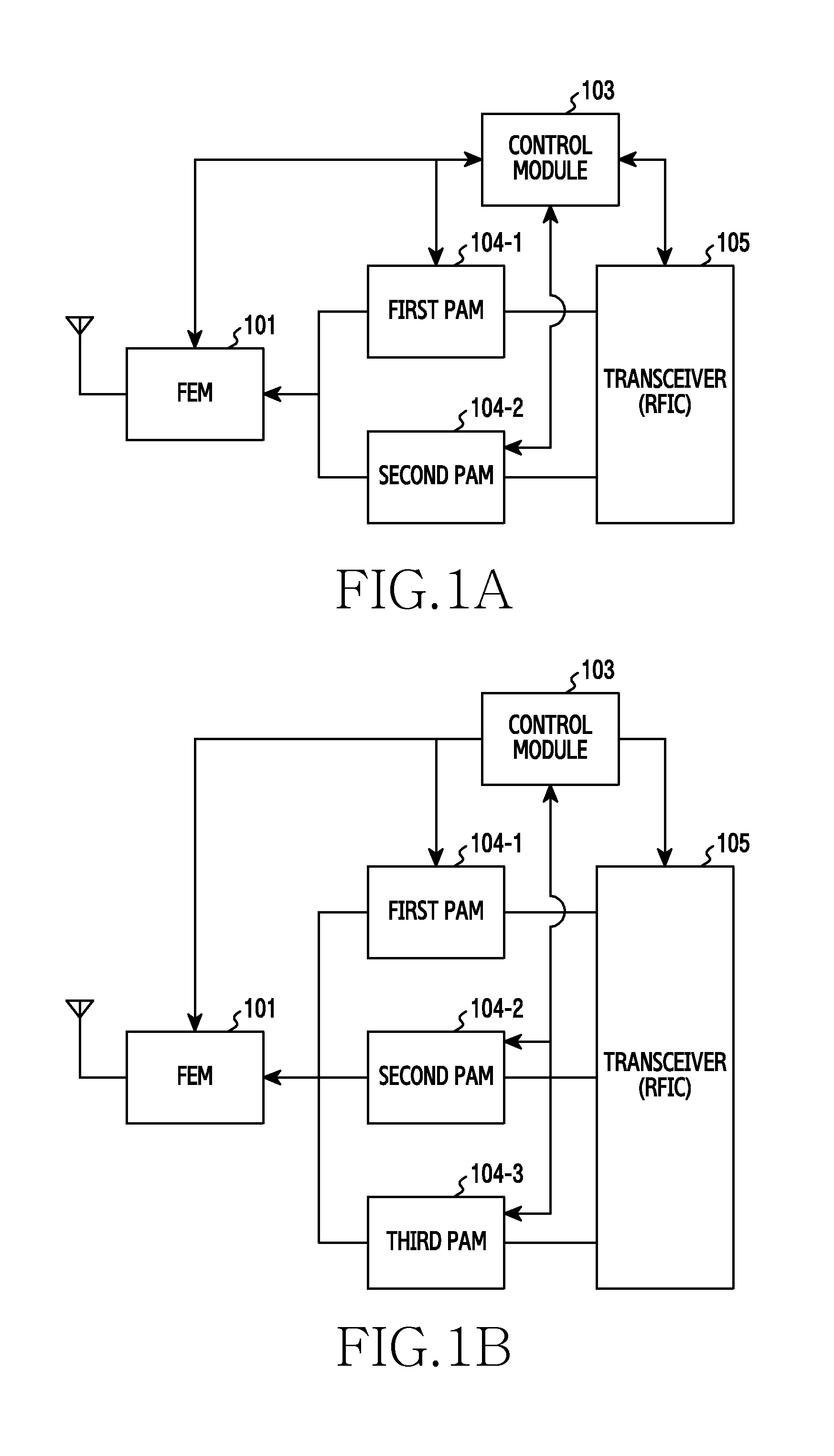
[0031]FIG. 1A illustrates a transmitter according to an embodiment of the present disclosure.

[0032]Referring to FIG. 1A, a transmitter includes a Front End Module (FEM) 101, a control module 103, a first PAM 104-1, a second PAM 104-2, and a transceiver 105. Although illustrated as separate components, at least two ...


PUM


Abstract

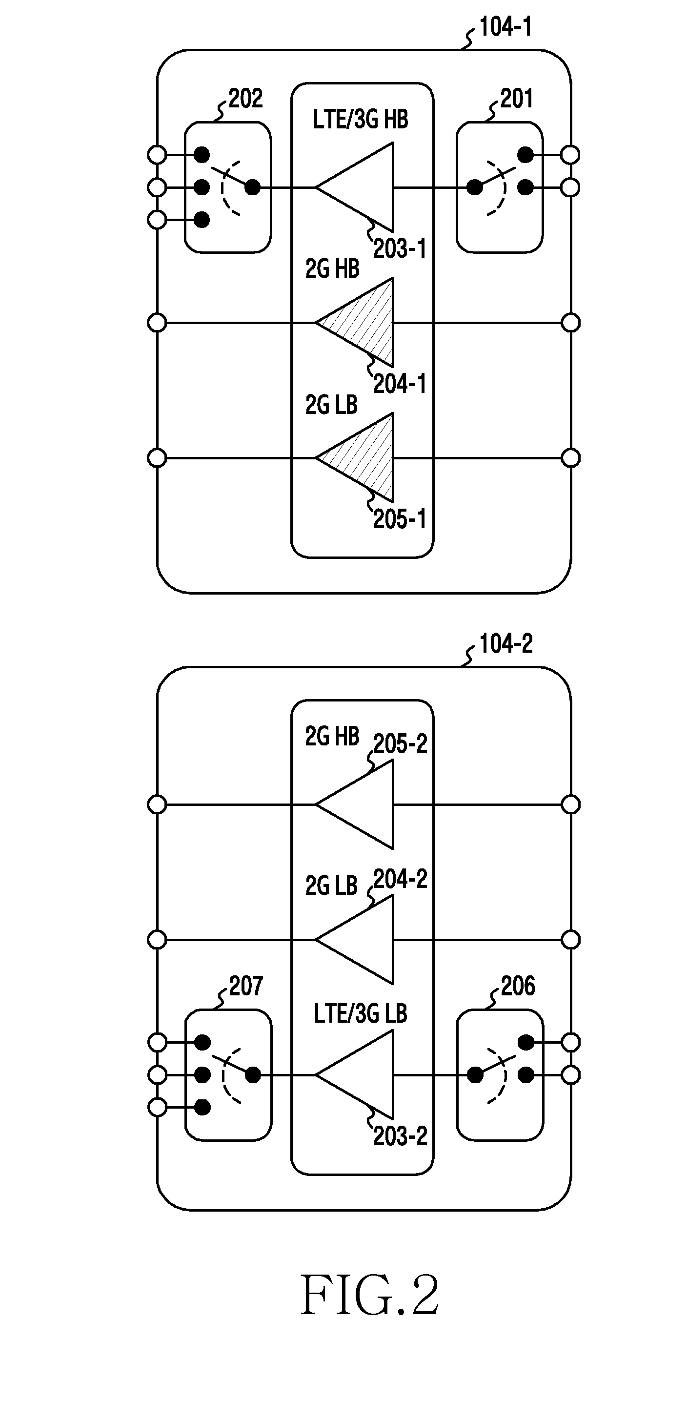
A transmitter and method are provided for processing a transmission signal. The transmitter includes an FEM that switches a plurality of band signals for a first and second communication scheme, wherein the band signals for the first communication scheme include a first HB signal, a second HB signal, a first LB signal, and a second LB signal, and the band signals for the second communication scheme include a third LB and a third HB signal; a first PAM including a first power amplifier that amplifies the third HB signal, a second power amplifier that amplifies the first HB signal, and a third power amplifier that amplifies the first LB signal; and a second PAM including a fourth power amplifier that amplifies the third LB signal, a fifth power amplifier that amplifies the second HB signal, and a sixth power amplifier that amplifies the second LB signal.

Description

PRIORITY[0001]This application claims priority under 35 U.S.C. §119(a) to Korean Application Serial No. 10-2014-0127660, which was filed in the Korean Intellectual Property Office on Sep. 24, 2014, the entire content of which is hereby incorporated by reference.BACKGROUND[0002]1. Field of the Disclosure[0003]The present disclosure relates generally to a transmitter and, more particularly, to a transmitter that supports a Multi-Mode Multi-Band (MMMB).[0004]2. Description of the Related Art[0005]Generally, a mobile communication service is provided in different communication service schemes around the world and uses multiple frequency bands for each communication service scheme. For example, the different mobile communication service schemes include a Personal Communication Service (PCS), a Digital Cellular System (DCS), a Code Division Multiple Access (CDMA) scheme, a Global System for Mobile communication (GSM) / General Packet Radio Service (GPRS) / Enhanced Data rates for GSM Evolutio...

Claims


Application Information

Patent Timeline
Patent Type & Authority Applications(United States)
IPC IPC(8): H04B1/00
CPCH04B1/006H04W88/06H04B1/0067H04B1/02
Inventor PARK, CHANG-JOON
Owner SAMSUNG ELECTRONICS CO LTD
Learn More