Methods and systems for contactless battery discharging

a technology of contactless battery and discharging system, which is applied in the direction of charging/discharging, electric power transfer ac network, transportation and packaging, etc., can solve the problems of limiting affecting the reliability of battery power levels, and affecting the mobility of rechargeable batteries for extended periods

Active Publication Date: 2016-03-24
MOTOROLA SOLUTIONS INC
View PDF3 Cites 7 Cited by
  • Summary
  • Abstract
  • Description
  • Claims
  • Application Information

AI Technical Summary

Problems solved by technology

In a way, the rechargeable battery limits the mobility of these devices because it must be plugged in to specialized devices to undergo various forms of battery maintenance (e.g., such as battery recalibration).
As a result of the need for periodic maintenance, the mobility of these devices is compromised for extended durations (e.g., when the device is docked in a battery reconditioning system).
Without regular maintenance, reported battery power levels cannot be relied upon, and maximum charging capacity cannot be attained.
Such a process traditionally requires a hard connection and therefore inhibits the mobile nature of the device within which the battery is embedded.

Method used


Image

  • Methods and systems for contactless battery discharging
  • Methods and systems for contactless battery discharging
  • Methods and systems for contactless battery discharging

Examples


Embodiment Construction

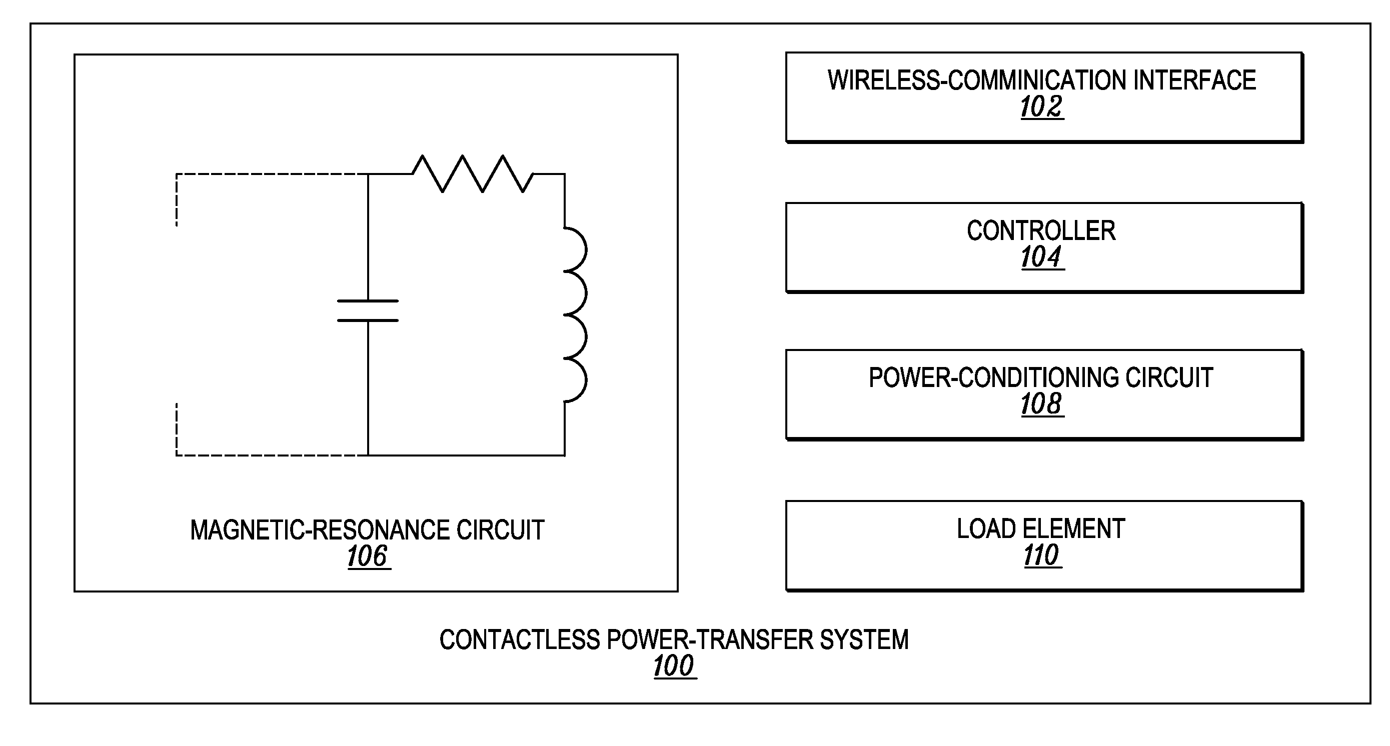
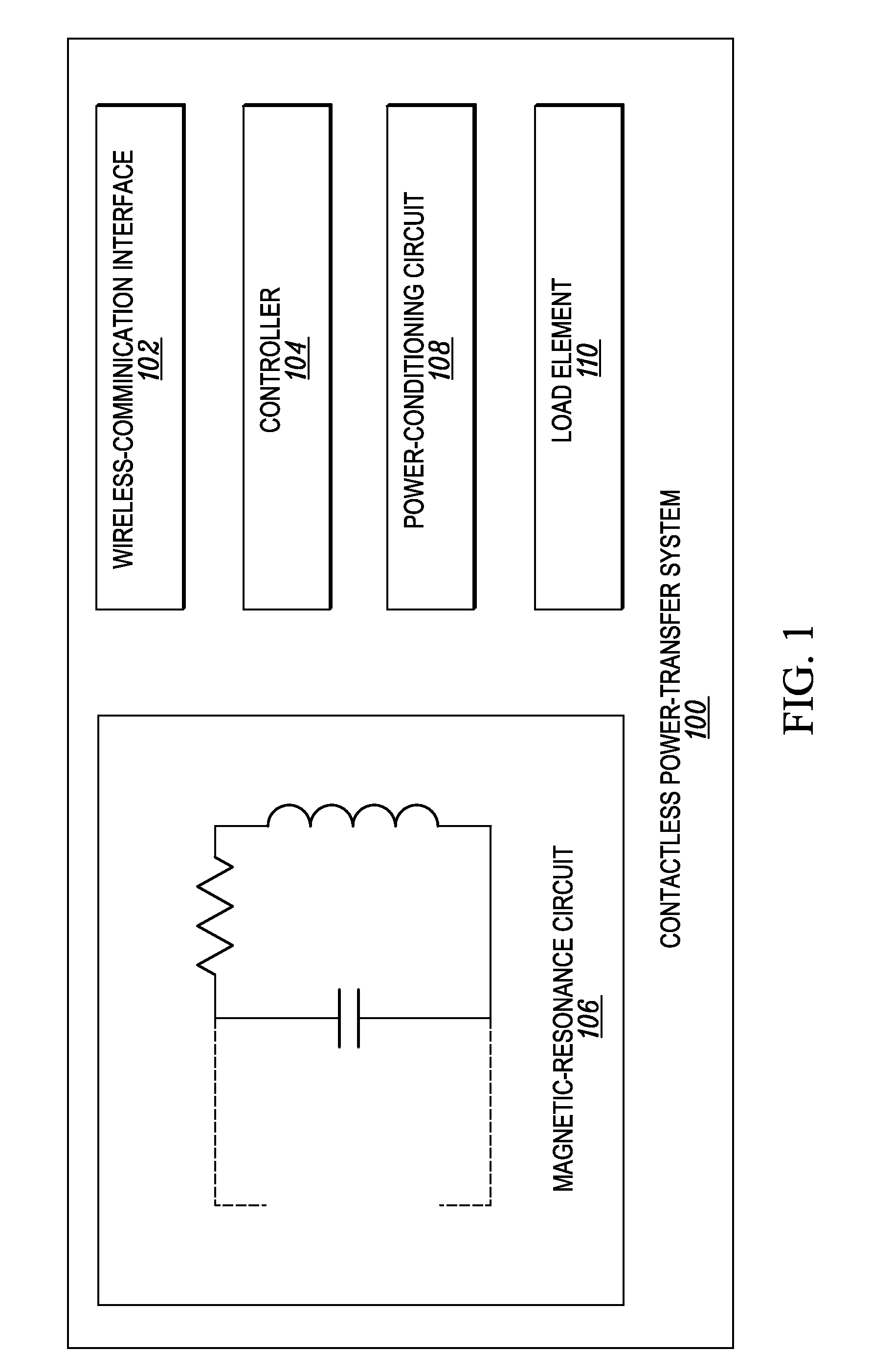
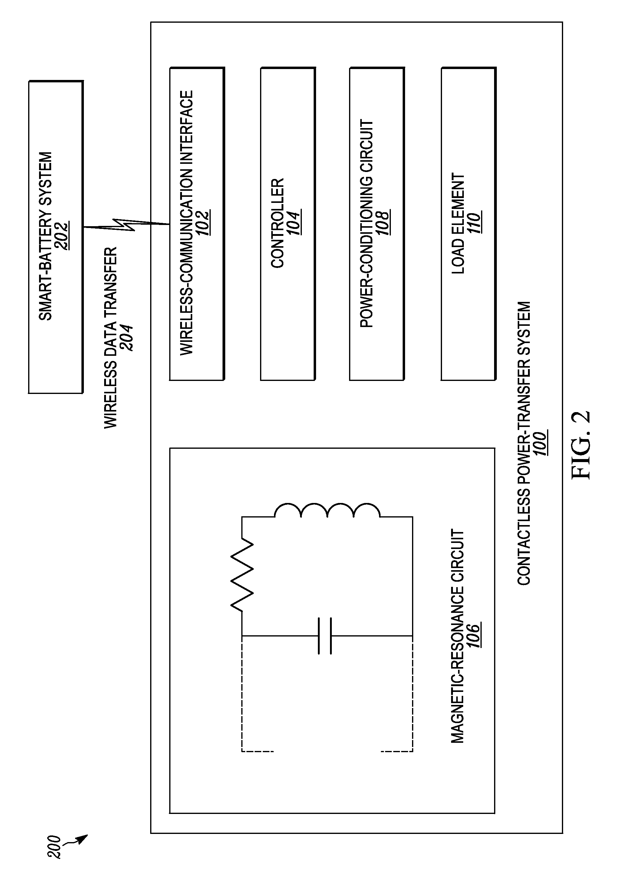
[0014]Disclosed herein are methods and systems for contactless battery discharge. One embodiment takes the form of a contactless power-transfer system that includes a wireless-communication interface, a controller connected to the wireless-communication interface, a magnetic-resonance circuit, a power-conditioning circuit connected to the magnetic-resonance circuit, and a load element connected to the power-conditioning circuit. The controller is configured to determine that a smart-battery system is in a discharge-needed state and responsively transmit, via the wireless-communication interface, a battery-discharge command instructing the smart-battery system to generate an oscillating magnetic field. The magnetic-resonance circuit is configured to couple with the generated oscillating magnetic field and responsively output a corresponding power signal. The power-conditioning circuit is configured to receive the power signal from the magnetic-resonance circuit, rectify the received ...


PUM


Abstract

Disclosed herein are methods and systems for contactless battery discharging. One embodiment takes the form of a contactless power-transfer system that includes a wireless-communication interface, a controller connected to the wireless-communication interface, a magnetic-resonance circuit, a power-conditioning circuit connected to the magnetic-resonance circuit, and a load element connected to the power-conditioning circuit. The controller is configured to determine that a smart-battery system is in a discharge-needed state and responsively transmit, via the wireless-communication interface, a battery-discharge command instructing the smart-battery system to generate an oscillating magnetic field. The magnetic-resonance circuit is configured to couple with the generated oscillating magnetic field and responsively output a corresponding power signal. The power-conditioning circuit is configured to receive the power signal from the magnetic-resonance circuit, rectify the received power signal, and output the rectified power signal. The load element is configured to receive the rectified power signal from the power-conditioning circuit.

Description

BACKGROUND OF THE INVENTION[0001]Mobility is important. Wireless-communication infrastructures have enabled the dawn of all sorts of devices that no longer require hardwired connections when sending and receiving data. Such devices, and many others, require electronic power to function; in many cases, this power comes from a rechargeable battery. Recently, wireless charging has emerged as an option for powering and recharging various devices. With wireless charging, the devices are less reliant on wired connections and the presence of traditional outlets. One method for wireless power transmission includes generating an oscillating magnetic field by using an AC signal to drive a solenoid or source coil. In such a system, a power transmitter is plugged into a wall outlet and a mobile device wirelessly receives power from it. The mobile device uses the changing magnetic flux to generate a current in a coil of its own.[0002]In a way, the rechargeable battery limits the mobility of thes...

Claims


Application Information

Patent Timeline
Patent Type & Authority Applications(United States)
IPC IPC(8): H04B5/00H02J5/00H02J7/00
CPCH04B5/0037H02J2007/0067H02J7/0063H02J5/005H02J7/025H02J7/0069H01M10/4257H02J3/36Y02E60/60H02J50/80H02J50/12H02J7/00
Inventor BRUMLEY, EDWARD, W.GEREN, MICHAEL, D.HERRMANN, JOHN, E.
Owner MOTOROLA SOLUTIONS INC
Why Eureka
Try Eureka