Vehicle

a supercharger and vehicle technology, applied in the field of vehicles including superchargers, can solve the problems of poor response of the turbo-type supercharger for enhancing engine power, small exhaust gas energy, and poor low-to-mid-speed range, so as to achieve desirable supercharger pressure characteristics, improve engine power, and keep the load on the crankshaft at start-up low

Active Publication Date: 2016-03-31
YAMAHA MOTOR CO LTD
View PDF18 Cites 6 Cited by
  • Summary
  • Abstract
  • Description
  • Claims
  • Application Information

AI Technical Summary

Benefits of technology

[0033]According to another preferred embodiment of the present invention, the vehicle is an off-road vehicle.
[0034]According to this preferred embodiment, it is possible to provide an off-road vehicle with the advantageous effects set forth above.
[0035]According to the preferred embodiments of the present invention, it is possible to provide a vehicle, with which it is possible to improve the engine power, to keep the load on the crankshaft at start-up low, and to achieve desirable supercharging pressure characteristics.
[0036]The above and other elements, features, steps, characteristics and advantages of the present invention will become more apparent from the following detailed description of the preferred embodiments with reference to the attached drawings.

Problems solved by technology

A turbo-type supercharger utilizes the energy of the exhaust gas, and when it is used in an off-road vehicle such as a snowmobile or a four-wheel buggy, the responsiveness is poor in the low- to mid-speed range where the energy of the exhaust gas is small.
That is, in the low- to mid-speed range, the effect of the turbo-type supercharger for enhancing the engine power does not respond well to the throttle control.
With a supercharger that is driven by the crankshaft, a vehicle that is normally used at a high engine speed, such as a snowmobile, will have an unnecessarily high supercharging pressure at a low speed.
The need to control the supercharging pressure so that the supercharging pressure will not be too high leads to a complicated structure.

Method used


Image

  • Vehicle
  • Vehicle
  • Vehicle

Examples


Embodiment Construction

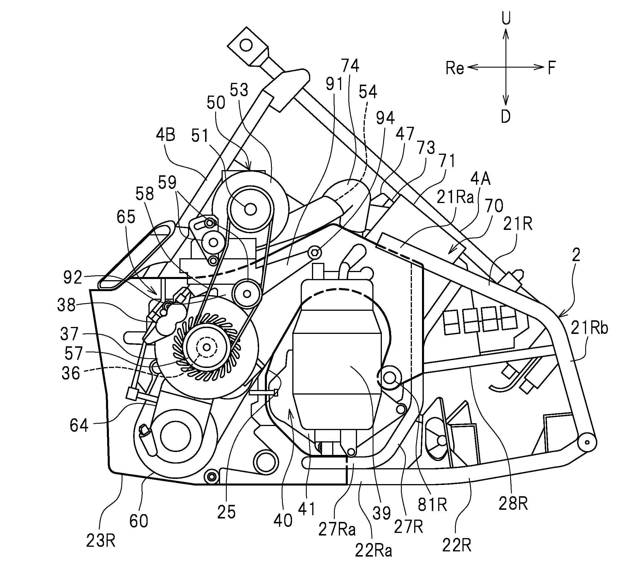
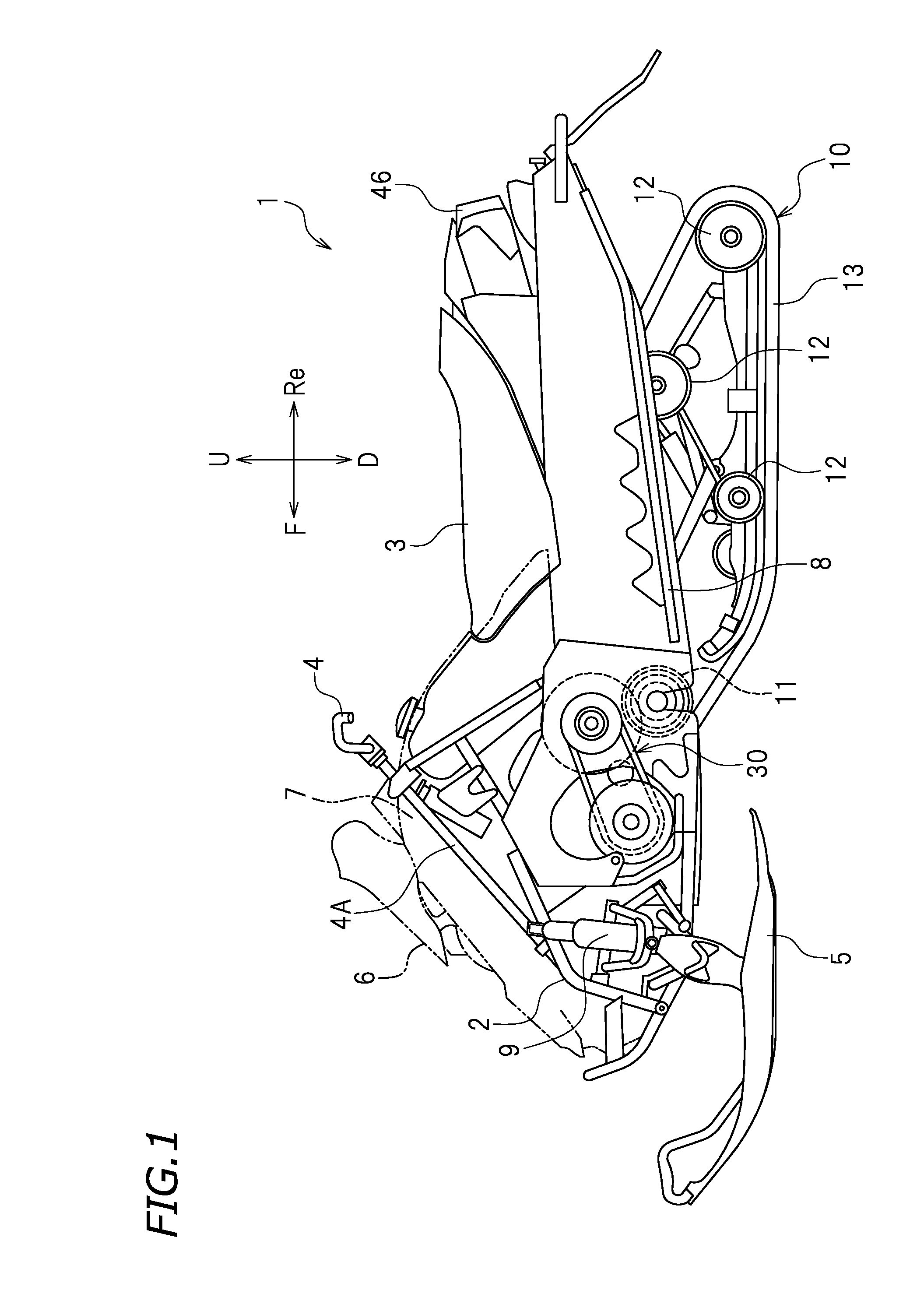
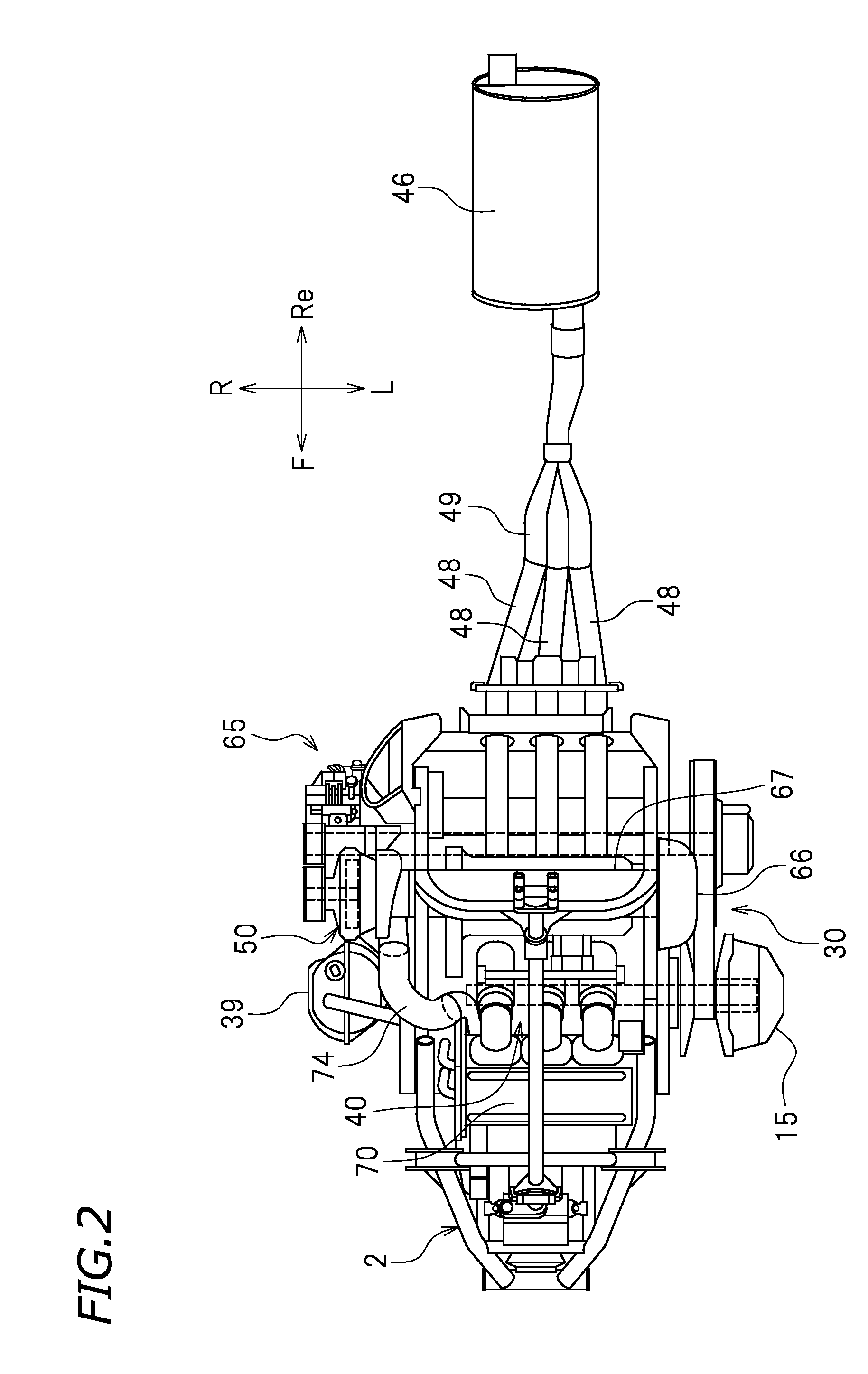
[0048]Preferred embodiments of the present invention will now be described. As shown in FIG. 1, a vehicle of the present embodiment is a snowmobile 1. The terms front, rear, left, right, up, and down, as used in the description below, refer to these directions as seen from a passenger seated in a seat 3 of the snowmobile 1, unless specified otherwise. The designations F, Re, L, R, U, and D, as used in the figures, refer to front, rear, left, right, up, and down, respectively.

[0049]The snowmobile 1 includes a frame 2, the seat 3 supported on the frame 2 in which a passenger is seated, a handle 4 operated by the passenger, and a pair of left and right skis 5. A steering shaft 4A is connected to the handle 4. Although not shown in the figures, the steering shaft 4A is linked to the left and right skis 5. A front cover 6 is provided forward of the seat 3. A left side cover 7 is located leftward of the front cover 6, and a right side cover (not shown) is located rightward of the front co...


PUM


Abstract

A vehicle includes a transmission including an input shaft linked to a crankshaft of an engine so that power is transmitted therebetween, and an output shaft which is able to rotate at a rotational speed lower than a rotational speed of the input shaft. The snowmobile includes a driving device linked to the output shaft so that power is transmitted therebetween to generate a driving power, a supercharger including a rotation shaft linked to the output shaft so that power is transmitted therebetween, and a centrifugal clutch located between the crankshaft and the input shaft or between the output shaft and the rotation shaft.

Description

[0001]The present application claims priority to Japanese Patent Application No. 2014-197455, filed on Sep. 26, 2014, the disclosure of which is hereby incorporated by reference in its entirety.BACKGROUND OF THE INVENTION[0002]1. Field of the Invention[0003]The present invention relates to a vehicle including a supercharger.[0004]2. Description of the Related Art[0005]A supercharger has been used in order to improve the engine power in vehicles such as snowmobiles and four-wheel buggies. U.S. Pat. No. 7,198,127 discloses a snowmobile including a turbo-type supercharger that utilizes the energy of the exhaust gas from the internal combustion engine. U.S. Patent Application Publication No. 2007 / 0102215 discloses a snowmobile including a mechanical supercharger that is driven by the crankshaft of the internal combustion engine.[0006]A turbo-type supercharger utilizes the energy of the exhaust gas, and when it is used in an off-road vehicle such as a snowmobile or a four-wheel buggy, th...

Claims


Application Information

Patent Timeline
Patent Type & Authority Applications(United States)
IPC IPC(8): F02B39/04B60K5/04B62M9/06B62M27/02F02B33/40F02B39/12F02B61/00
CPCF02B39/04F02B33/40F02B39/12B62M2027/023B62M9/06B62M27/02B60K5/04F02B61/00B60Y2200/252Y02T10/12
Inventor KAI, MANABUNAKAMURA, AKIHIKO
Owner YAMAHA MOTOR CO LTD
Why Eureka
Try Eureka