Electricity generating and air conditioning system

a technology of electric power generation and air conditioning system, applied in the direction of defrosting, heating types, domestic cooling apparatus, etc., can solve the problems of low energy efficiency of the system, and achieve the effects of enhancing the energy efficiency, and enhancing the power of the engin

Inactive Publication Date: 2006-02-23
LG ELECTRONICS INC
View PDF18 Cites 10 Cited by
  • Summary
  • Abstract
  • Description
  • Claims
  • Application Information

AI Technical Summary

Benefits of technology

[0016] The electricity generating and air conditioning system according to the present invention has an advantage in that the first generator coupled to the output shaft of the engine generates electricity, the turbo charger is operated by exhaust gas discharged from the engine, to enhance the power of the engine, and the second generator coupled to the turbo charger generates electricity, so that it is possible to achieve an enhancement in energy efficiency.
[0017] In the electricity generating and air conditioning system according to the present invention, the first generator coupled to the output shaft of the engine generates electricity. The turbo charger is operated by exhaust gas discharged from the engine, to enhance the power of the engine. Also, the exhaust gas used to operate the turbo charger also may rotate the electricity-generating turbine, so that the second generator coupled to the electricity-generating turbine generates electricity. Accordingly, it is possible to minimize the load of the turbo charger and to achieve an enhancement in energy efficiency.
[0018] The electricity generating and air conditioning system according to the present invention also has an advantage in that heat of the exhaust gas discharged from the engine is recovered, and is supplied to the discharge line of the compressor, to heat a refrigerant passing through the compressor discharge line, so that an improvement in the heating performance of the indoor heat exchanger is achieved.
[0019] The electricity generating and air conditioning system according to the present invention also has an advantage in that heat of cooling water used to cool the engine is recovered to pre-heat air blown to the outdoor heat exchanger, so that it is possible to prevent the outdoor heat exchanger from being frosted, and to achieve an enhancement in heating performance.
[0020] The electricity generating and air conditioning system according to the present invention includes a heater to pre-heat a refrigerant passing through the suction line of the compressor, using the electricity generated from at least one of the first and second generators, so that it is possible to enhance the heating performance of the indoor heat exchanger or to reduce the power consumption of the compressor in accordance with the pre-heating operation of the pre-heater.

Problems solved by technology

However, such a conventional electricity generating and air conditioning system has a problem in that exhaust gas generated during an electricity generating operation of an engine is discharged to the atmosphere without being again used for generation of electricity, so that the system exhibits a low energy efficiency.

Method used


Image

  • Electricity generating and air conditioning system
  • Electricity generating and air conditioning system
  • Electricity generating and air conditioning system

Examples


third embodiment

[0090] In a heating operation of the air conditioner 20 in the electricity generating and air conditioning system having the above-described arrangement the directional valve 45 is switched to a heating mode. In this case, the heat medium circulation pump 58 is driven for recovery of waste heat of exhaust gas, and the cooling water circulation pump 9 and heat medium circulation pump 68 are driven for recovery of waste heat of cooling water. The compressor 41 and heater 48 are also driven, using electricity generated from the first and second generators 10 and 30.

first embodiment

[0091] The switching operation of the directional valve 45 to the heating mode, the refrigerant circulation achieved in accordance with the operation of the compressor 41, and the heating operation achieved in accordance with the refrigerant circulation are the same as those in the first embodiment, so that no detailed description thereof will be given.

[0092] When the heat medium circulation pump 58 operates, the heat medium, which has been heated by exhaust gas in the exhaust gas waste heat recovering heat exchanger 52, is fed to the compressor discharge line heater 54 via the heat medium circulation conduit 58, so that the heat medium releases heat into the compressor discharge line heater 54. Thereafter, the heat medium is circulated into the exhaust gas waste heat recovering heat exchanger 52 via the heat medium circulation conduit 57.

[0093] During the circulation of the heat medium, the compressor discharge line heater 54 heats high-temperature and high-pressure refrigerant ga...

fifth embodiment

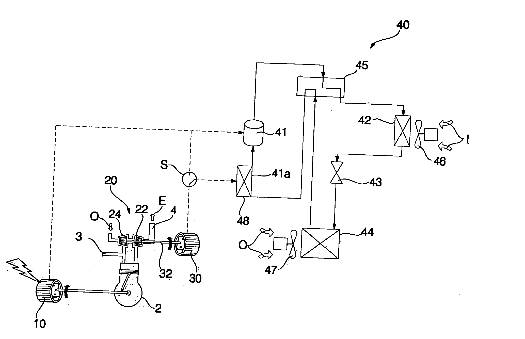
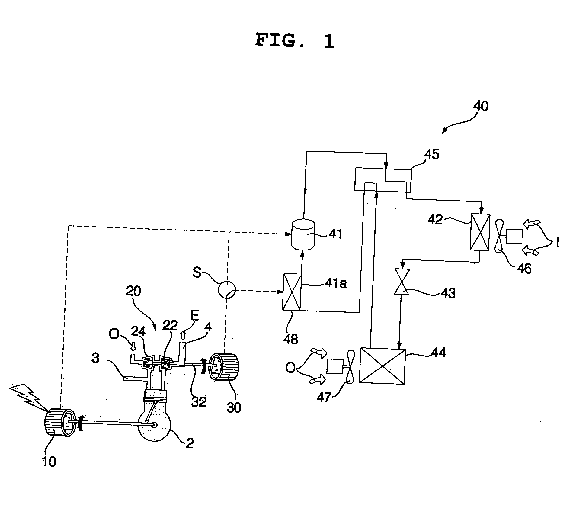
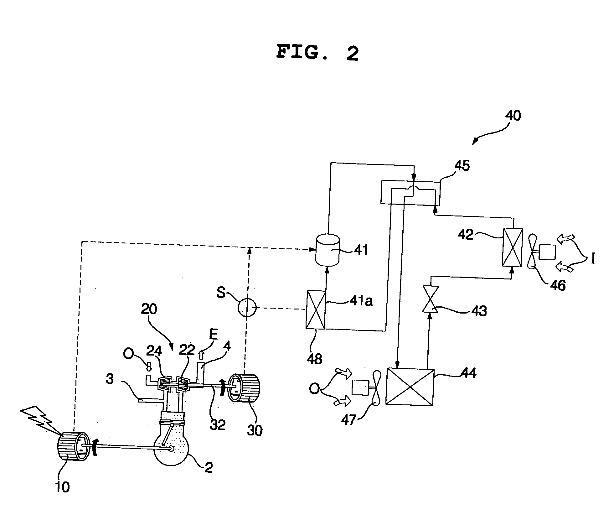
[0104]FIG. 9 is a schematic diagram of an electricity generating and air conditioning system according to the present invention, illustrating a state in which the system operates in a heating mode.

[0105] As shown in FIG. 9, the electricity generating and air conditioning system includes a heater 48′ to heat a refrigerant passing through a discharge line 41b of the compressor 41. The electricity generating and air conditioning system of the fifth embodiment has the same configuration and functions as those of the first embodiment or third embodiment, except for the heater 48′. Accordingly, the constituent elements of the fifth embodiment respectively corresponding to those of the first embodiment or third embodiment are designated by the same reference numerals, and no detailed description thereof will be given.

[0106] In the electricity generating and air conditioning system of this embodiment, the refrigerant, which passes through the discharge line 41b of the compressor 41 during ...


PUM


Abstract

An electricity generating and air conditioning system including a first generator coupled to the output shaft of the engine to generate electricity, a turbo charger to be operated by exhaust gas discharged from the engine, and thus, to enhance the power of the engine, and a second generator coupled to the turbo charger to generate electricity, so that it is possible to achieve an enhancement in energy efficiency.

Description

BACKGROUND OF THE INVENTION [0001] 1. Field of the Invention [0002] The present invention relates to an electricity generating and air conditioning system which generates electricity, using an engine, and uses the electricity in an air conditioner, and, more particularly, to an electricity generating and air conditioning system in which exhaust gas generated during an electricity generating operation of an engine is used to again generate electricity. [0003] 2. Description of the Related Art [0004] In general, electricity generating and air conditioning systems generate electricity by use of a rotating force outputted from an engine, and operate an air conditioner by use of the generated electricity. Such electricity generating and air conditioning systems are mainly used for multi-type air conditioners or large-scale air conditioners. [0005] Such electricity generating and air conditioning systems include an engine, a generator connected to an output shaft of the engine to generate...

Claims


Application Information

Patent Timeline
Patent Type & Authority Applications(United States)
IPC IPC(8): F25B27/00
CPCF25B13/00F25B2500/02F25B2400/06F25B27/02F25D21/04F24F1/00F25B1/00F28D7/00Y02A30/274
Inventor KANG, SEUNG TAKCHOI, CHANG MINCHOI, WON JAELIM, HYUNG SOOHWANG, YOON JEI
Owner LG ELECTRONICS INC
Why Eureka
Try Eureka