Thermal type flow rate measurement apparatus

a flow rate measurement and flow rate technology, applied in the direction of machines/engines, electrical control, instruments, etc., can solve problems such as errors in output signals, and achieve the effects of improving driving performance and productivity, reducing variation in correction, and improving accuracy of flow rate measurements during pulsation or respons

Active Publication Date: 2009-11-03
HITACHI ASTEMO LTD
View PDF15 Cites 9 Cited by
  • Summary
  • Abstract
  • Description
  • Claims
  • Application Information

AI Technical Summary

Benefits of technology

[0023]According to the present invention, during pulsation or transient response of flow rates, the accuracy of flow rate measurements during pulsation or response is improved without losing signal characteristics properly sensed by a sensor. In particular, it is possible to realize a flow rate meter in which variation in correction can be reduced under execution of correction for response recovery. In motor vehicle application, improving the driving performance and productivity can easily be achieved. In engine control application, by decreasing measurement errors during pulsation at a high engine speed, engine power improvement and more accurate control can be performed and reduced exhaust gas and improved fuel consumption can be achieved.

Problems solved by technology

These factors cause an error in an output signal.

Method used


Image

  • Thermal type flow rate measurement apparatus
  • Thermal type flow rate measurement apparatus
  • Thermal type flow rate measurement apparatus

Examples


first embodiment

[0109] as described above, the following advantages are provided: pulsation errors in the sensor output of the thermal type flow rate meter can be decreased; and restrictions (restriction factors such as throttle opening and engine speed) for the user on using the present sensor are reduced. Also, it is possible to realize a flow rate meter in which variation in response delay correction (response delay rectification) is reduced and improving the driving performance and productivity of motor vehicles can easily be achieved.

[0110]Next, a second embodiment of the present invention is described, referring to FIG. 12. This is an example of a flow rate meter using a frequency signal as an output signal fout (corresponding to Vout in the first embodiment) of the sensor 4.

second embodiment

[0111]Difference from the foregoing embodiment is that a digital-frequency converter (D / F converter) 28 is used instead of the D / A converter 24 to output a signal and the second embodiment has a feature that signal superimposition is easy to do, as signals in pulses are handled. The controller 5 is provided with a timer 53 for frequency counting and is configured such that a reference signal Tref such as a crank angle of the engine can be taken in to the controller. The response of an output signal fout from the sensor can be selected and switching to a reference clock signal fck can be performed optionally, as is the case in the foregoing embodiment.

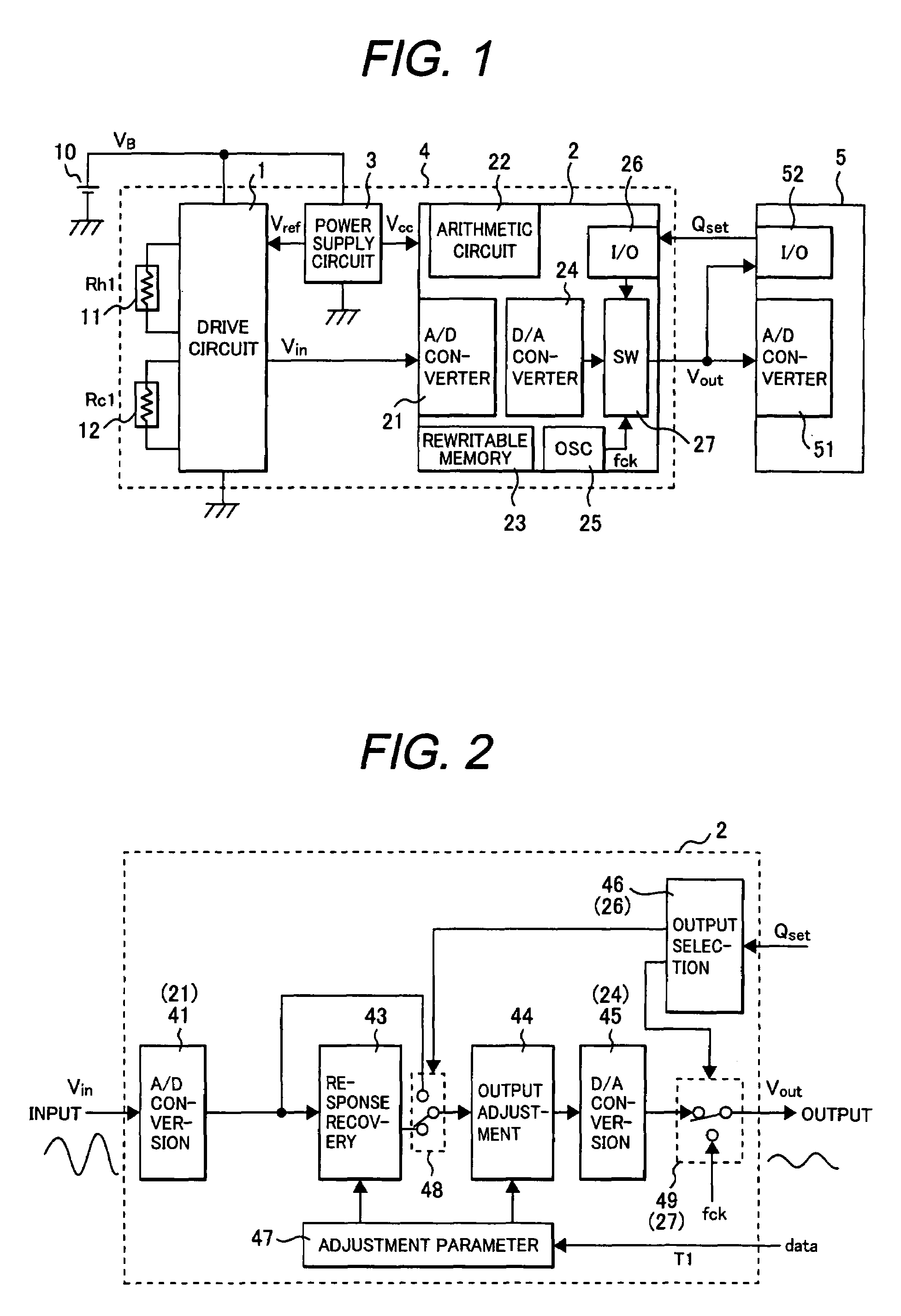
[0112]A flow of detailed arithmetic processing is explained, referring to FIG. 13. The digital processing device 2 takes in an output Vin of the sensor 1, converts the analog input signal into a digital value by analog-digital conversion processing 41, optionally performs response recovery processing 43 by digital means, and performs ou...

third embodiment

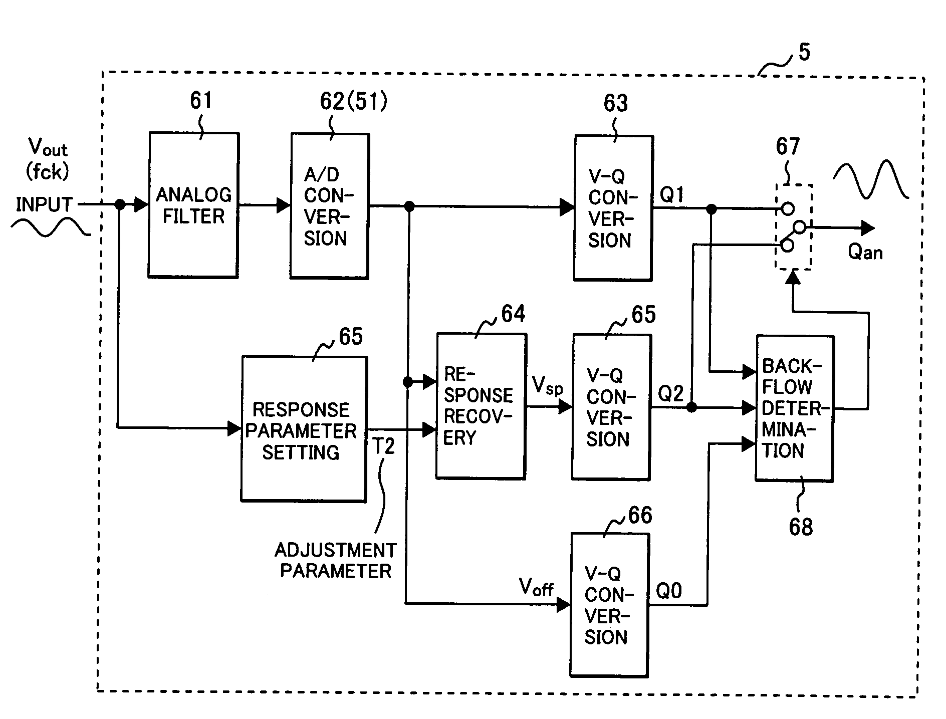
[0125]FIG. 15 illustrates details of arithmetic processing of the digital processing device 2 in the flow rate sensor 4 in the invention.

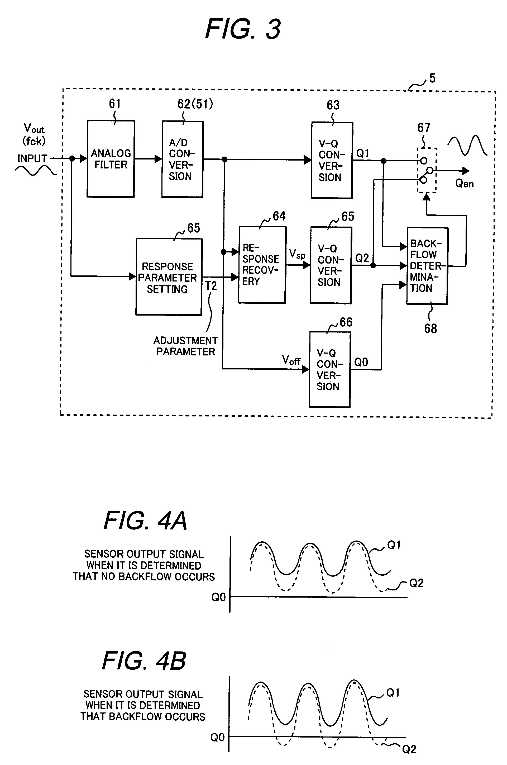
[0126]In the third embodiment, the flow rate sensor 4 itself (digital processing device 2) determines whether a backflow occurs. The digital processing device 2 takes in an output Vin of the drive circuit 1 and converts it into a digital value by analog-digital conversion 41. The converted digital value is processed as Vin1 directly by output adjustment processing 44 through a soft switch (selector switch) 48 or processed by response recovery processing 43 by digital means (a signal having response recovery is referred to as Vin2) and, then, processed by the output adjustment processing 44.

[0127]The signal processed by the output adjustment processing 44 is converted into an analog signal by a digital-analog converter 45 and output.

[0128]In this embodiment, backflow determination processing 47 for selecting whether or not to execute the response re...


PUM


Abstract

Thermal type flow rate meters for measuring the flow rate of intake air of an internal combustion engine of a motor vehicle or the like have encountered a problem of an increase in pulsation errors during high engine speed and high pulsation. Meanwhile, digitally recovering responses has posed a problem in which pulsation performance is liable to become worse, affected by variation in a clock or the like. The sensor is provided with means for transferring a response variation factor to the engine control unit. The engine control unit is provided with logics for automatically determining the variation factor and correcting a response. Means for detecting a backflow occurrence is provided and a parameter for a response recovery is changed before and after a backflow occurrence. The sensor is provided with a selecting means by which a sensor response can be selected and obtained and the engine control unit is provided means for allowing selection of a response.

Description

TECHNICAL FIELD[0001]The present invention relates to a thermal type flow rate measurement apparatus for measuring a flow rate of a fluid such as air.BACKGROUND ART[0002]Thermal type air flow rate measurement apparatus (a thermal type air flow meter), which has thermal sensitive resistors such as a heating resistor and temperature compensating resistor having a temperature characteristic, is cable of directly measuring a mass air flow rate. Therefore, it is widely diffused to measure a flow rate of an intake air for an internal combustion engine of a motor vehicle or the like. A signal of the measured air flow rate is provided for, e.g., calculating a fuel injection quantity of an electronically controlled fuel injector.[0003]As a thermal sensitive resistor such as a heating resistor, a hot wire flowmeter, which is configured by winding a platinum wire on a bobbin and coating the wound bobbin with glass, is widely diffused for practical use. In addition to that, in recent years, a t...

Claims


Application Information

Patent Timeline
Patent Type & Authority Patents(United States)
IPC IPC(8): G06F19/00F02D35/00F02D41/18F02D45/00G01F1/00G01F1/68G01F1/684G01F1/696G01F1/72
CPCG01F1/6845G01F1/72G01F1/6965
Inventor KANKE, ATSUSHI
Owner HITACHI ASTEMO LTD
Why Eureka
Try Eureka