Combustion engine waste heat powered air-conditioning system

a technology of air-conditioning system and combustion engine, which is applied in the field of air-conditioning system, can solve the problems of increasing the cost of fuel consumption of vehicles, contributing to vehicle exhaust emission, and needless use of world fuel supply, so as to save 0.5 hp of engine power, improve the reliability of the overall system, and eliminate the cost of electric driven pump or belt driven pump system.

Inactive Publication Date: 2013-10-10
KAPICH DAVORIN
View PDF15 Cites 8 Cited by
  • Summary
  • Abstract
  • Description
  • Claims
  • Application Information

AI Technical Summary

Benefits of technology

[0010]In some embodiment the costs associated with electric driven pump or belt driven pump systems can be eliminated, saving an additional 0.5 HP of engine power and greatly improves reliability of the overall system by simp

Problems solved by technology

With average specific fuel consumption of approximately 0.55 lb/HP-hr this translates into approximately three dollars per hour fuel cost just

Method used


Image

  • Combustion engine waste heat powered air-conditioning system
  • Combustion engine waste heat powered air-conditioning system
  • Combustion engine waste heat powered air-conditioning system

Examples


second preferred embodiment

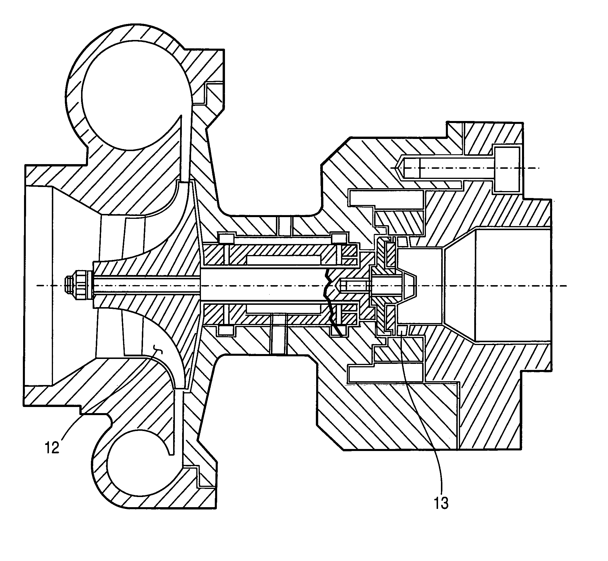
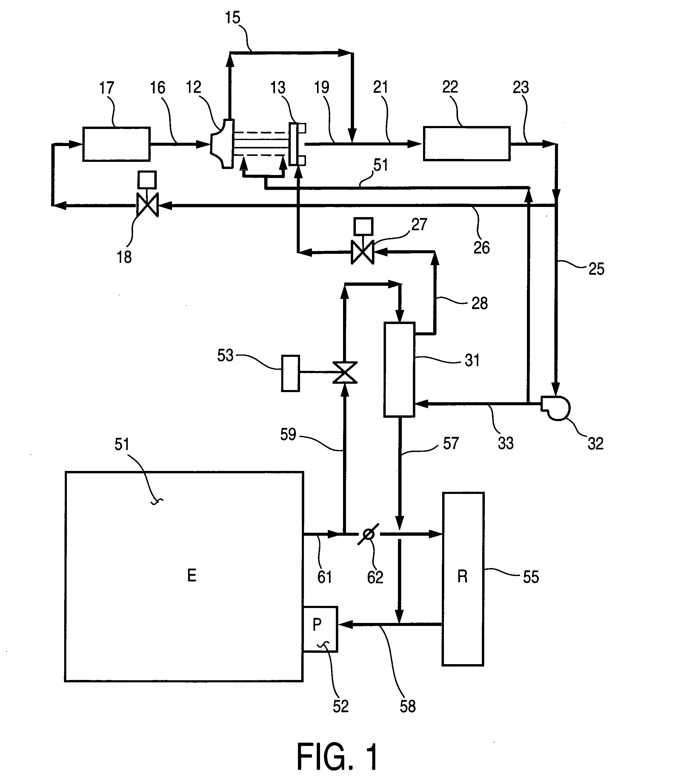
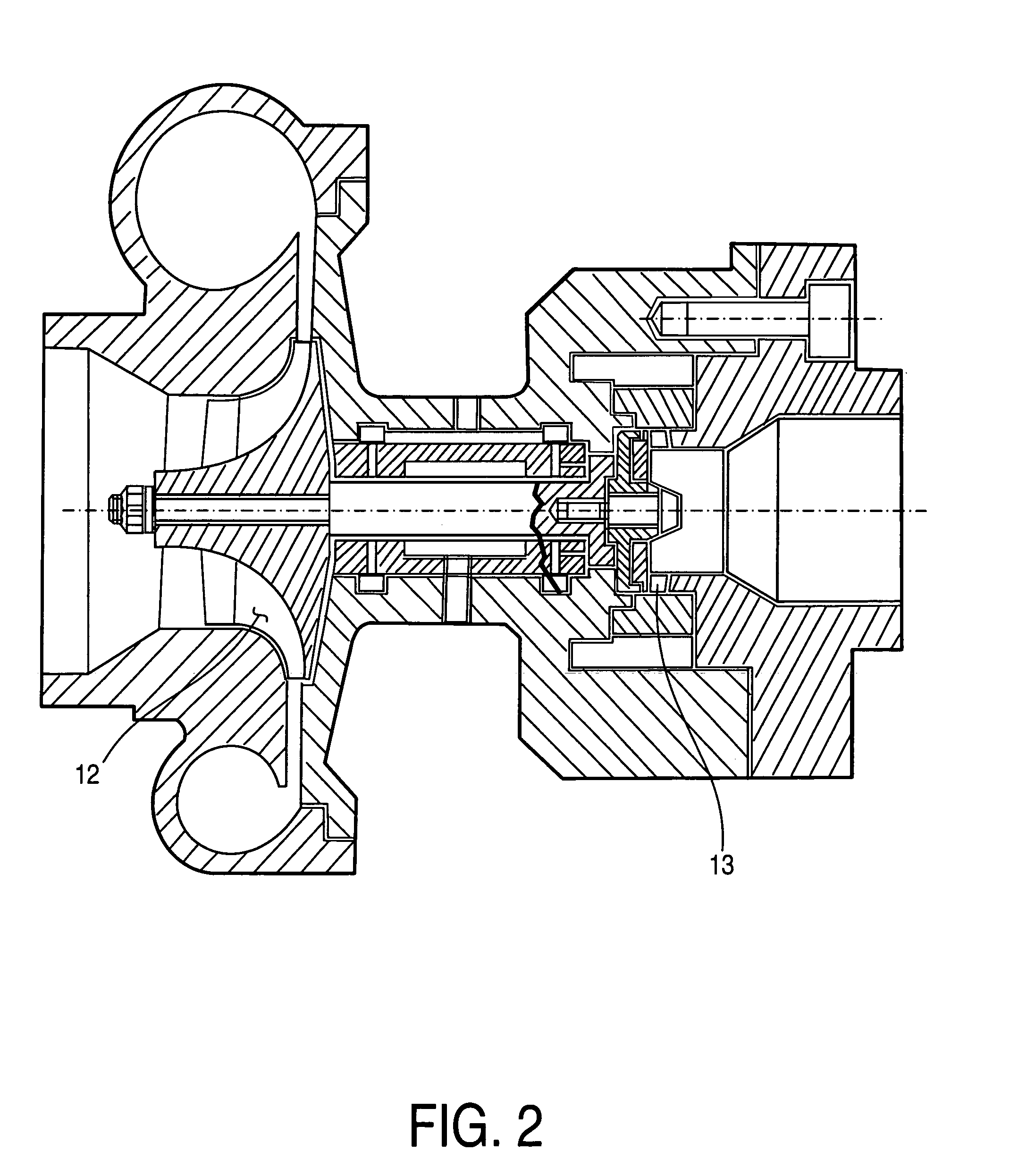
[0031]FIG. 7 shows second preferred system embodiment which is similar to the first preferred embodiment shown in FIG. 1 with exception that refrigerant pump 32 which is electric driven or belt driven by the engine shown in FIG. 1 is being replaced by high speed refrigerant pump 81 that is driven by refrigerant vapor turbine 82 as shown in FIG. 7. Refrigerant pump 81 and refrigerant vapor turbine 82 rotor is supported on liquid refrigerant hydrostatic journal bearings in the same fashion as refrigerant turbo-compressor 12 rotor shown in FIG. 3, thus avoiding need for oil lubrication.

[0032]Thermal analysis of engine coolant and refrigerant system has shown that amount of engine coolant waste heat available in typical heavy duty diesel engine is more than sufficient to generate refrigerant vapor in refrigerant boiler 31 to drive both compressor drive turbine 13 and refrigerant pump drive turbine 82.

[0033]In case of 4 ton air conditioning system the compressor drive turbine 13 produces...


PUM


Abstract

An air conditioning system in which a high-pressure refrigerant vapor turbine is driving a low-pressure high-speed centrifugal compressor both supported on liquid refrigerant hydrostatic journal bearings. Due to required turbine miniaturization, the turbine blades surface finish and blade accuracy are of critical importance in order to produce high turbine adiabatic efficiency.

Description

CROSS REFERENCE TO RELATED APPLICATIONS[0001]This application claims the benefit of Provisional Patent Application Ser. No. 61 / 517,1-2 filed Apr. 13, 2011.FIELD OF THE INVENTION[0002]This invention relates to air conditioning systems and in particular to such systems based on the use of waste heat.BACKGROUND OF THE INVENTION[0003]Conventional air-conditioning systems in motor vehicles utilize predominantly direct driven refrigerant compressors which provides suction pressure causing evaporation of liquid refrigerant in evaporator that produces cooling capacity to the air flow circulated through the vehicle interior. Compressor vapor discharge is condensed in a condenser where it is usually cooled by ambient air. Condensed liquid is further expanded through a throttle valve back into the evaporator thus forming a closed loop.[0004]Typical direct driven air-conditioning system in a hot climate uses approximately 1 kW of engine power per 1 ton cooling capacity, equivalent to 12,000 BTU...

Claims


Application Information

Patent Timeline
IPC IPC(8): F25B27/02
CPCF25B27/02B60H1/3222B60H1/18F25B1/053Y02A30/274
Inventor KAPICH, DAVORIN
Owner KAPICH DAVORIN
Why Eureka
Try Eureka