Fuel supply apparatus for internal combustion engine

a fuel supply apparatus and internal combustion engine technology, applied in mechanical equipment, liquid fuel feeders, machines/engines, etc., can solve the problems of reducing the idling speed, the fuel supply apparatus cannot meet the demand for further reducing the pulsation, and the difficulty in controlling the pulsation resonance frequency, so as to effectively suppress the pulsation of fuel pressur

Inactive Publication Date: 2016-03-31
TOYOTA JIDOSHA KK
View PDF9 Cites 5 Cited by
  • Summary
  • Abstract
  • Description
  • Claims
  • Application Information

AI Technical Summary

Benefits of technology

[0025]According to the present invention, fuel-pressure pulsation in the low-pressure-side fuel passage, which is caused by an operation of the high-pressure fuel pump, is damped by the pulsation damping element in the vicinity of the high-pressure fuel pump, and also the fuel-pressure pulsation, having passed through the pulsation damping element, is reduced by the orifice. Thus, fuel-pressure pulsation, propagated from the hi

Problems solved by technology

It is difficult to control the pulsation resonance frequency by changing the length of a fuel pipe from the high-pressure fuel pump to a low-pressure fuel injection mechanism.
Thus, the fuel supply apparatus cannot meet the demand for further reducing pulsation with a reduction in idling speed.
Further, in a case where a so-called fuel-cut process is performed at the time of deceleration at a high engine speed, for example, at the time of downhill driving, the frequency of fuel-pressure pulsation in a l

Method used


Image

  • Fuel supply apparatus for internal combustion engine
  • Fuel supply apparatus for internal combustion engine
  • Fuel supply apparatus for internal combustion engine

Examples


first embodiment

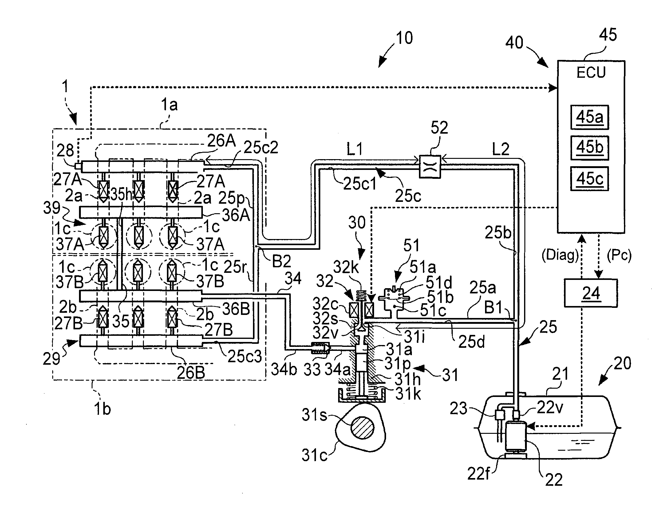
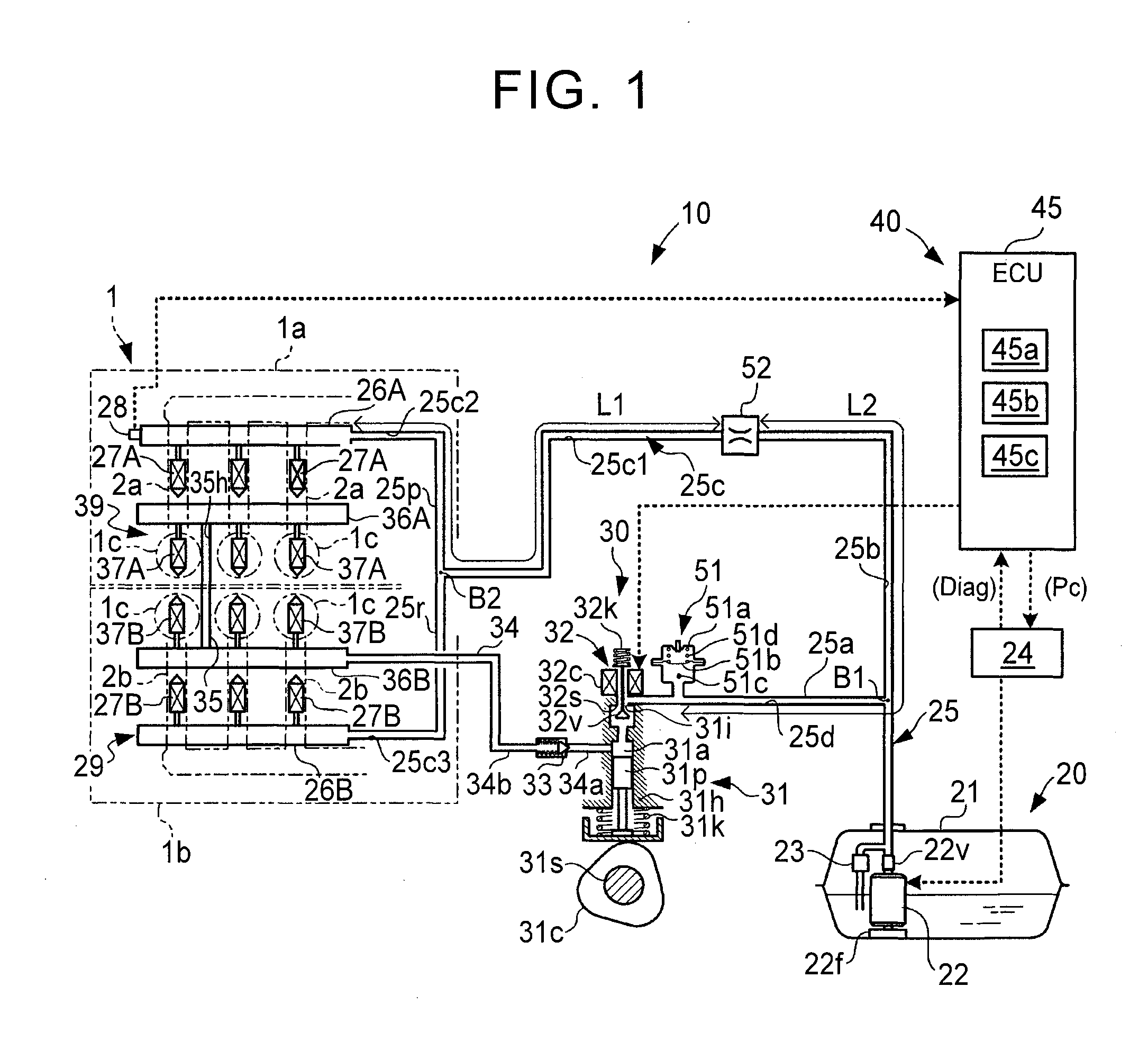
[0031]FIG. 1 shows a fuel supply apparatus for an internal combustion engine according to the present invention.

[0032]An engine 1 according to the present embodiment shown in FIG. 1 is configured as a V-type six-cylinder engine (a multi-cylinder internal combustion engine) that is mounted on an automobile (a vehicle). The engine 1 includes a first bank 1a and a second bank 1b, each of which includes three cylinders 1c. In each of the cylinders 1c, a piston is accommodated, a combustion chamber is defined, and an intake valve and an exhaust valve are provided so as to be opened and closed at a predetermined timing. The piston, the combustion chamber, the intake valve, and the exhaust valve are not shown in FIG. 1. In the engine 1, an ignition device, including an ignition plug that is exposed to the interior of the combustion chamber, and an ignition coil that is used to cause the ignition plug to be ignited, is installed, for example. Also, a fuel supply apparatus 10 according to th...

second embodiment

[0100]FIG. 3 shows a fuel supply apparatus for an internal combustion engine according to the present invention.

[0101]In the fuel supply apparatus according to the second embodiment, a pulsation damping element is added on the inlet side of the low-pressure fuel injection mechanism 29, in contrast to the fuel supply apparatus 10 according to the first embodiment. Other than that, the fuel supply apparatus according to the second embodiment has the same configuration as the first embodiment. Therefore, in FIG. 3, the constituent elements of the fuel supply apparatus according to the second embodiment, which are the same as those in the first embodiment, are denoted by the same reference numerals as those of the corresponding constituent elements in FIG. 1. Particularly different points are described below.

[0102]In a fuel supply apparatus 60 according to the present embodiment, the passage portion 25c1, located on the low-pressure fuel injection mechanism 29-side relative to the orifi...


PUM


Abstract

A fuel supply apparatus for an internal combustion engine includes a low-pressure fuel injection mechanism, a high-pressure fuel injection mechanism, a low-pressure fuel pump, a high-pressure fuel pump, a first pulsation damping element, and an orifice. The first pulsation damping element is provided in a passage, located on. the high-pressure fuel pump-side, in a “fuel pipe interposed between the high-pressure fuel pump and the low-pressure fuel injection mechanism. The orifice is provided in the passage, located on the low-pressure fuel injection mechanism-side relative to the first pulsation damping element, in the fuel pipe.

Description

BACKGROUND OF THE INVENTION[0001]1. Field of the Invention[0002]The present invention relates to a fuel supply apparatus for an internal combustion engine, and particularly relates to a fuel supply apparatus for an internal combustion engine, which can perform direct fuel injection into a cylinder of the internal combustion engine and fuel injection into an intake port thereof.[0003]2. Description of Related Art[0004]In an internal combustion engine for driving a vehicle to run, which is capable of performing fuel injection into an intake port (hereinafter, referred to as “port injection”) and direct fuel injection into a cylinder (hereinafter, referred to as “cylinder injection”), a fuel supply apparatus that uses a high-pressure fuel pump to pressurize fuel from a feed pump to a high pressure is provided. As the high-pressure fuel pump, a mechanical pump that reciprocates a plunger is frequently used.[0005]In the fuel supply apparatus for an internal combustion engine as described...

Claims


Application Information

Patent Timeline
IPC IPC(8): F02M55/04F02M69/04
CPCF02M69/046F02M55/04F02M2200/315
Inventor YUASA, TAKAO
Owner TOYOTA JIDOSHA KK
Why Eureka
Try Eureka