Color sets for low resolution dithering in reflective color displays

a color display and color set technology, applied in the field of color sets for low resolution dithering in reflective color displays, can solve the problems of preventing their widespread use, inadequate service life of these displays, gas-based electrophoretic media being susceptible to the same types of problems, etc., and achieves the effects of reducing the spatial resolution of the image rendered on the display, increasing color depth, and reducing the dithering

Active Publication Date: 2016-03-31
E INK CORPORATION
View PDF3 Cites 21 Cited by
  • Summary
  • Abstract
  • Description
  • Claims
  • Application Information

AI Technical Summary

Benefits of technology

[0036]The present invention seeks to provide a method for rendering a full-color image on a reflective display capable of providing a palette of colors at each pixel location that comprises fewer colors than are required to render an image on the display as a whole (i.e., the colors available at the pixel level are quantized at a coarser level than those required to render an image of sufficient quality for a particular application). The method of the invention involves dithering between colors that are available in each pixel's color palette, in such a way that the spatial resolution of the image rendered on the display is reduced but the color depth increased. Such dithering is well-known in the printing art. When a dithered image is viewed at a sufficient distance, the individual colored pixels are merged by the human visual system into perceived uniform colors. Because of the trade-off between color depth and spatial resolution, dithered images when viewed closely have a characteristic graininess as compared to images in which the color palette available at each pixel location has the same depth as that required to render images on the display as a whole.

Problems solved by technology

Nevertheless, problems with the long-term image quality of these displays have prevented their widespread usage.
For example, particles that make up electrophoretic displays tend to settle, resulting in inadequate service-life for these displays.
Such gas-based electrophoretic media appear to be susceptible to the same types of problems due to particle settling as liquid-based electrophoretic media, when the media are used in an orientation which permits such settling, for example in a sign where the medium is disposed in a vertical plane.
Indeed, particle settling appears to be a more serious problem in gas-based electrophoretic media than in liquid-based ones, since the lower viscosity of gaseous suspending fluids as compared with liquid ones allows more rapid settling of the electrophoretic particles.
The inherent disadvantage of area sharing is that the colorants are always present, and colors can only be modulated by switching the corresponding pixels of the underlying monochrome display to white or black (switching the corresponding primary colors on or off).
Area sharing is especially problematic when mixing yellow because it is lighter than any other color of equal brightness, and saturated yellow is almost as bright as white.
Such a complex arrangement of electrodes is costly to manufacture, and in the present state of the art it is difficult to provide an adequately transparent plane of pixel electrodes, especially as the white state of the display must be viewed through several layers of electrodes.
Multi-layer displays also suffer from parallax problems as the thickness of the display stack approaches or exceeds the pixel size.
However, there are disadvantages to the use of multiple electrophoretic layers located between a single set of addressing electrodes.
In addition, optical losses in an electrophoretic layer closest to the viewing surface (for example, caused by light scattering or unwanted absorption) may affect the appearance of images formed in underlying electrophoretic layers.
None of these patent applications disclose full color display in the sense in which that term is used below.
Some of the aforementioned displays do provide full color but at the cost of requiring addressing methods that are long and cumbersome.
See also U.S. Patent Application Publication No. 2011 / 0134506 and the aforementioned application Ser. No. 14 / 277,107; the latter describes a full color display using three different types of particles in a colored fluid, but the presence of the colored fluid limits the quality of the white state which can be achieved by the display.
Although such displays are typically capable of rendering multiple colors at every pixel location (for example, black, white, the three subtractive primary colors (cyan, magenta and yellow) and the three additive primary colors (red, green and blue), in the current state of the art they are not capable of rendering colors corresponding to 256 RGB levels at every pixel location.
Such algorithms may involve error diffusion, a technique in which error resulting from the difference between the color required at a certain pixel and the closest color in the per-pixel palette (i.e., the quantization residual) is distributed to neighboring pixels that have not yet been processed.

Method used


Image

  • Color sets for low resolution dithering in reflective color displays
  • Color sets for low resolution dithering in reflective color displays
  • Color sets for low resolution dithering in reflective color displays

Examples


Embodiment Construction

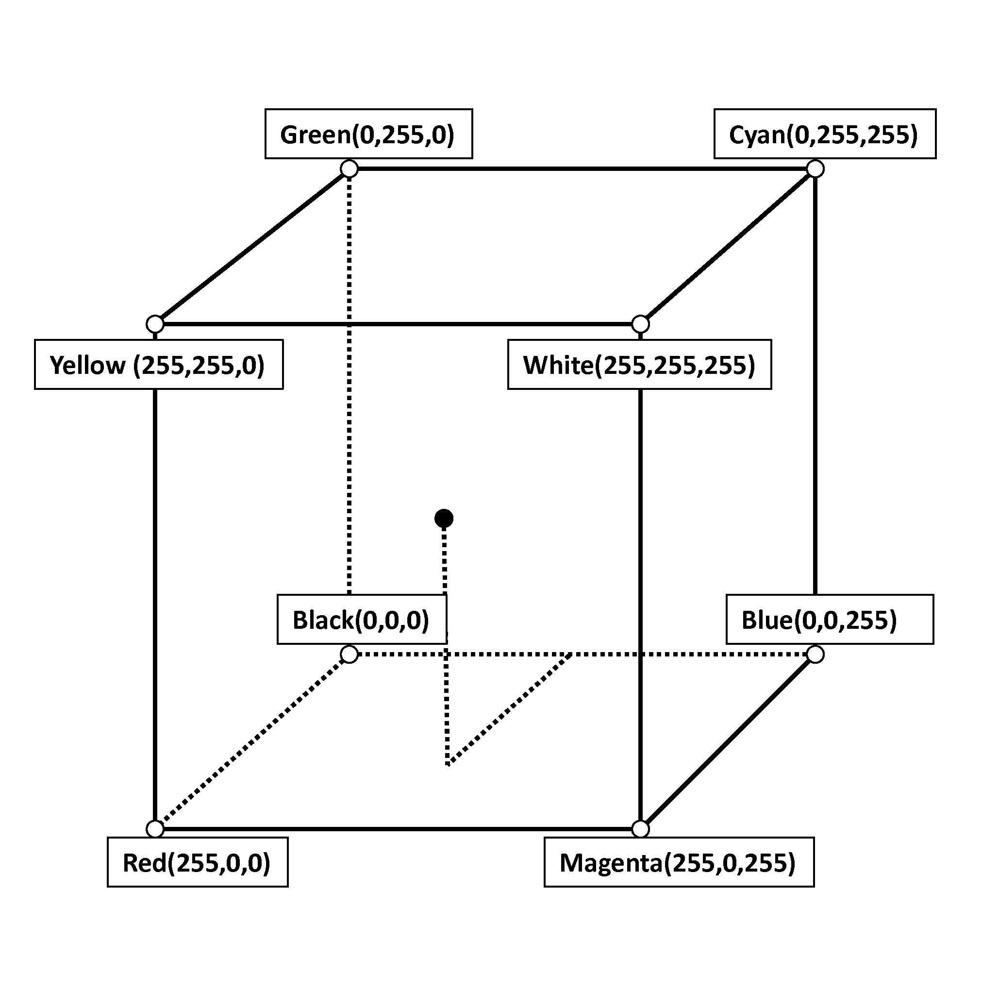
[0053]One type of reflective display is an electrophoretic display containing an electrophoretic medium. An electrophoretic medium comprises a fluid, a first, light scattering particle (typically white) and second, third and fourth particles having three subtractive primary colors (typically magenta, cyan and yellow); at least two of these colored particles being non-light scattering. The first and second particles bear polymer coatings such that the electric field required to separate an aggregate formed by the third and the fourth particles is greater than that required to separate an aggregate formed from any other two types of particles. Methods for driving the medium to produce white (“W”), black (“K”), magenta (“M”), cyan (“C”), yellow (“Y”), red (“R”), green (“G”) and blue (“B”) colors are also described.

[0054]FIG. 1 of the accompanying drawings is a schematic cross-section showing the positions of the various particles in an electrophoretic medium of the present invention wh...


PUM

PropertyMeasurementUnit
ODaaaaaaaaaa
ODaaaaaaaaaa
optical densityaaaaaaaaaa

Abstract

The present invention provides for a method of rendering an image on a reflective display wherein each pixel is capable of rendering a limited number of colors, each of which is rendered by predetermined set of waveforms stored in a waveform lookup table. Furthermore, the present invention provides for a method for rendering an image using such colors, having been chosen for optimal color rendition. This invention further provides for rendering a color image formed from a plurality of pixels on a reflective display wherein each pixel has a color selected from the group consisting of at least: red, green, blue, cyan, magenta, yellow, black and white.

Description

[0001]This application claims benefit of copending Application Ser. No. 62 / 056,302, filed Sep. 26, 2014.[0002]This application is related to copending application Ser. No. 14 / 849,658, filed Sep. 10, 2015. The entire contents of this copending application and of all U.S. patents and published and copending applications mentioned below are herein incorporated by reference.BACKGROUND OF INVENTION[0003]The present invention provides for a method for rendering a colored image on a reflective display, wherein at each pixel location it is possible to render one of a predetermined palette of colors.[0004]The term color as used herein includes black and white. White particles are often of the light scattering type.[0005]The term gray state is used herein in its conventional meaning in the imaging art to refer to a state intermediate two extreme optical states of a pixel, and does not necessarily imply a black-white transition between these two extreme states. For example, several of the E In...

Claims


Application Information

Patent Timeline
Patent Type & Authority Applications(United States)
IPC IPC(8): G02F1/167
CPCG02F1/167G09G3/344G02F2001/1678G02F2201/52G09G3/2003G09G3/2044G09G2310/08G09G2340/06
Inventor BOUCHARD, ALAINTELFER, STEPHEN, J.
Owner E INK CORPORATION
Why Eureka
Try Eureka