Apparatus and method for producing objects utilizing three-dimensional printing

a three-dimensional printing and apparatus technology, applied in the direction of mechanical vibration separation, butter manufacturing, manufacturing environment conditioning, etc., can solve the problems of thermal solidification systems that are subject to both warping or curling, thermal stress and shock, and parts made by these techniques are still exposed to excessive thermal shock when being built in these environments, so as to reduce warping and internal stress of the article

Inactive Publication Date: 2016-04-07
TE CONNECTIVITY CORP
View PDF7 Cites 35 Cited by
  • Summary
  • Abstract
  • Description
  • Claims
  • Application Information

AI Technical Summary

Benefits of technology

[0013]An embodiment is directed to a three-dimensional printing apparatus. The apparatus includes an enclosure with a build chamber. A print head is provided in the build chamber. The print head deposits material to form an article. A first heating device is positioned proximate the print head. The first heating device heats ambient air in the build chamber to a first temperature which acts as a temperature sink for cooling of the article. A heated build plate is positioned in the build chamber. The heated build plate has a second heating device which heats a surface of the heated build plate on which the article is fabricated. The second heating device heats the top surface of the heated build plate to a second temperature which is higher than the first temperature. The first and second temperatures are controlled to minimize warping and thermal stress of the article.
[0014]An embodiment includes a third device provided to supply energy to a bond site in which the material extruded from the print head is deposited on a previously deposited layer of the article, wherein the energy facilitates the bonding of the material to the previously deposited layer.
[0015]An embodiment includes a fourth device provided to supply energy to heat only a previously deposited top layer of the article deposited on the heated build plate, wherein the energy facilitates the bonding of the material to the previously deposited top layer.
[0017]An embodiment is directed to a method for the fabrication of an article made using a three-dimensional printing process. The method includes depositing material from a print head onto a build plate located in a build chamber to form an article, heating ambient air in the build chamber to a first temperature which acts as a proper sink temperature for cooling of the article and heating the build plate to a second temperature which is higher than the first temperature. The first and second temperatures are controlled to minimize warping and thermal stress of the article.
[0021]An embodiment is directed to a method for the fabrication of an article to minimize warping and internal stress of the article. The method includes dispensing said thermally solidifiable material in a fluid state from a print head into a build chamber having a build plate, heating ambient air in the build chamber to a first temperature which acts as a proper sink temperature for cooling of the thermally solidifiable material and heating the build plate to a second temperature which is higher than the first temperature, the second temperature exceeding the solidification temperature of the thermally solidifiable material.

Problems solved by technology

Since most deposition materials change density with temperature, these systems share the challenge of minimizing geometric distortions of the product prototypes that are produced by these density changes.
Thermally solidifiable systems are subject to both warping or curling and thermal stress and shock due to plastic deformation and the like.
However, while the controlled build environment or the heated bed concept which directly heats the part being built help to control warping or curling, parts made by these techniques are still exposed to excessive thermal shock when being built in these environments.

Method used


Image

  • Apparatus and method for producing objects utilizing three-dimensional printing
  • Apparatus and method for producing objects utilizing three-dimensional printing
  • Apparatus and method for producing objects utilizing three-dimensional printing

Examples


Embodiment Construction

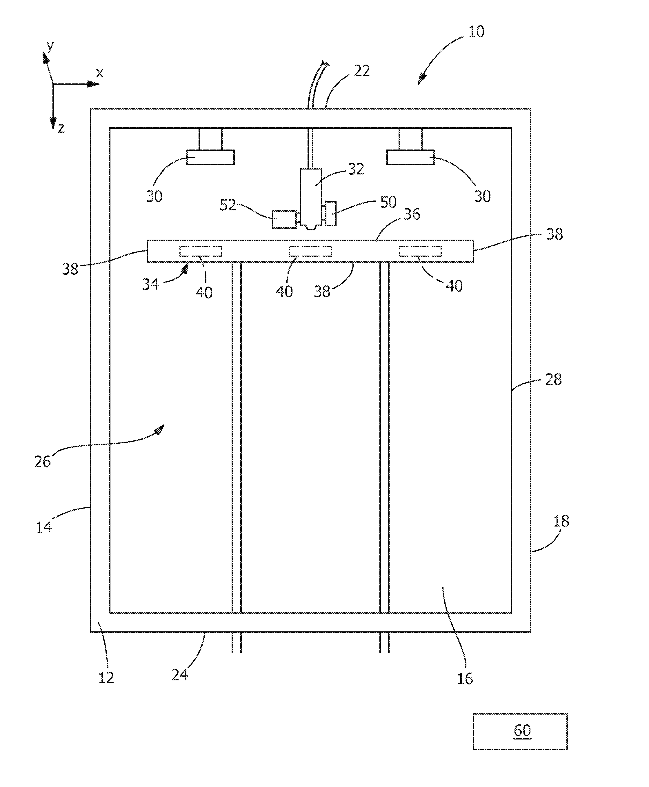
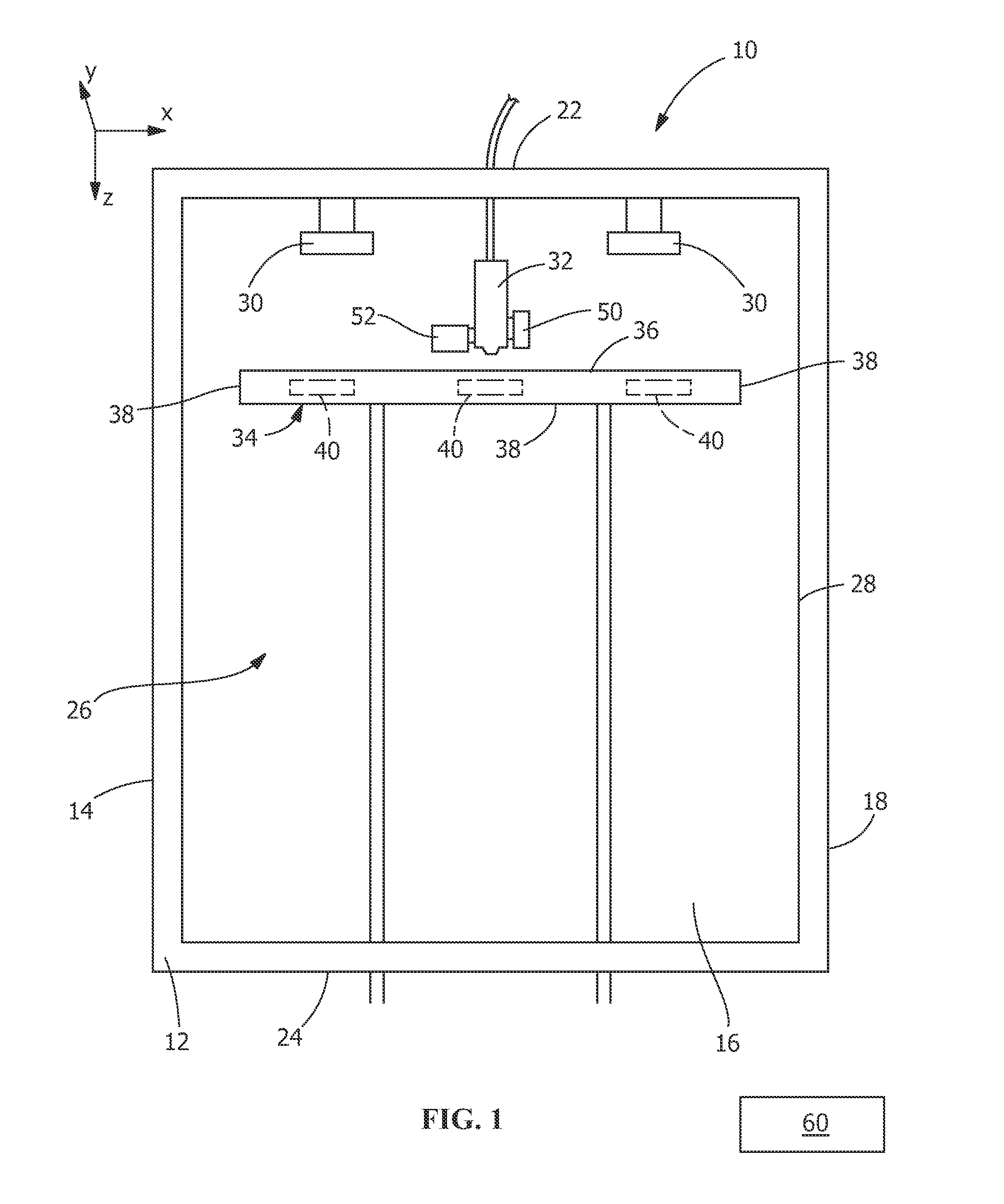
[0025]The description of illustrative embodiments according to principles of the present invention is intended to be read in connection with the accompanying drawings, which are to be considered part of the entire written description. In the description of embodiments of the invention disclosed herein, any reference to direction or orientation is merely intended for convenience of description and is not intended in any way to limit the scope of the present invention. Relative terms such as “lower,”“upper,”“horizontal,”“vertical,”“above,”“below,”“up,”“down,”“top” and “bottom” as well as derivative thereof (e.g., “horizontally,”“downwardly,”“upwardly,” etc.) should be construed to refer to the orientation as then described or as shown in the drawing under discussion. These relative terms are for convenience of description only and do not require that the apparatus be constructed or operated in a particular orientation unless explicitly indicated as such. Terms such as “attached,”“affi...


PUM

PropertyMeasurementUnit
temperatureaaaaaaaaaa
temperaturesaaaaaaaaaa
temperatureaaaaaaaaaa

Abstract

A method and apparatus for the fabrication of an article made using a three-dimensional printing process. The invention includes depositing material from a print head onto a build plate located in a build chamber to form an article, heating ambient air in the build chamber to a first temperature which acts as a proper sink temperature for cooling of the article, and heating the build plate to a second temperature which is higher than the first temperature. The first and second temperatures are controlled to minimize warping and thermal stress of the article.

Description

FIELD OF THE INVENTION[0001]The present invention is directed to a method and an apparatus for the production of a three-dimensional object in which the warping and thermal stress of the object are minimized. In particular, the invention is directed to a method and apparatus for providing a build environment in which the ambient environmental temperature and the build plate temperatures are individually controlled, thereby allowing the two parameters in the printing process to be decoupled from each other.BACKGROUND OF THE INVENTION[0002]It is common in metal and / or plastic parts manufacturing to produce large batch sizes and serial parts by injection molding or extrusion. The advantage of plastic injection molding is, in particular, owing to the highly accurate production of complex part geometries, whereby the functionality of the injection molding process optimally satisfies the requirements for the cost-effective and economical production of plastic parts.[0003]However, the need...

Claims


Application Information

Patent Timeline
Patent Type & Authority Applications(United States)
IPC IPC(8): B29C67/00
CPCB29C67/0085B33Y30/00B33Y10/00B29C67/0055B29C64/364B29C64/295B29C64/118B29C64/106
Inventor FRY, CHARLES DAVIDLOCONDRO, JOSEPHNAWARE, GAURANG N.
Owner TE CONNECTIVITY CORP
Why Eureka
Try Eureka