Apparatus for light intensity adjustment

a technology of light intensity adjustment and apparatus, which is applied in the field of apparatus for light intensity adjustment, can solve the problems of inability to efficiently control the intensity of light, the frame rate cannot be changed without re-initialization of the imager, and the high light conditions are too long, so as to avoid the stroboscopic effect, avoid the effect of stroboscopic effect, and operate accurately

Active Publication Date: 2016-04-07
SMR PATENTS S A R L
View PDF22 Cites 94 Cited by
  • Summary
  • Abstract
  • Description
  • Claims
  • Application Information

AI Technical Summary

Benefits of technology

[0013]In order to avoid a stroboscopic effect, one needs to keep the integration time as close to the time period between two consecutive read outs as possible. I.e. instead of reducing the integration time in the high light conditions, one should artificially reduce the intensity of the light that incidents the imager. In conventional photography, this is achieved by adjusting the diameter of stop inside the lens. The stop diameter is reduced, if the intensity of ambient light increases, and is increased, if the scene gets darker. Thus, the amount of light, accumulated by the pixels, remains within the optimal limits, and the overall image brightness is kept at a reasonable level.
[0052]The problem is further solved by a method for adjusting light intensity by an apparatus for light intensity adjustment mountable on an automotive camera, comprising at least one grey filter, which is arrangeable in front of a lens unit of an automotive camera such that incident light passes through the at least one grey before entering the lens unit of the automotive camera, providing the step: dimming the at least one grey filter to at least a frame rate of an image sensor of the an automotive camera, in particular such that the integration time of the sensor is maintained at the maximum.

Problems solved by technology

Some image sensors allow selection of a frame rate at system start up, however, typically, once selected, the frame rate cannot be changed without re-initialization of the imager.
And while for low light conditions 33 ms integration time might be adequate, it may be too long for high light conditions.
However, while solving the problem of imager adaptation to different lighting conditions, variable integration time causes a new problem, which is often refered to as stroboscopic effect.
This is because the intensity of light cannot be controlled efficiently by changing the voltage; instead pulse width modulation (PWM) is used.
If the flash occurs when the shutter is closed, the flash cannot be captured by the imager.
The situation, depicted in FIGS. 4a-4c, may cause safety problems for the driver.
Similarly, the driver will not be able to see with the mirror replacing camera LED day lights of the overtaking vehicles.
This may reduce the driver's ability to react on the road situation adequately and in time, and thus may result in a road accident.
However, mechanical stop mechanisms, integrated into the lenses, common in conventional photography are hardly applicable to the lenses, used in automotive cameras.
Secondly, the space, where the automotive camera is mounted, is typically very limited by the design of the surrounding components.
Building into such a miniature lens a highly reliable and durable stop mechanism that includes an actuator, is an extremely challenging task.
Apart from that, such a lens with adjustable stop diameter would be significantly more expensive than a similar lens with a fixed stop diameter.
Besides, a position sensor for sensing the position of the filters becomes redundant.

Method used


Image

  • Apparatus for light intensity adjustment
  • Apparatus for light intensity adjustment
  • Apparatus for light intensity adjustment

Examples


Embodiment Construction

[0068]In the following detailed description, reference is made to the accompanying drawings, which form a part thereof, and in which is shown by way of illustration specific aspects in which the disclosure may be practiced. It is understood that other aspects may be utilized and structural or logical changes may be made without departing from the scope of the present invention. The following detailed description, therefore, is not to be taken in a limiting sense, and the scope of the present invention is defined by the appended claims.

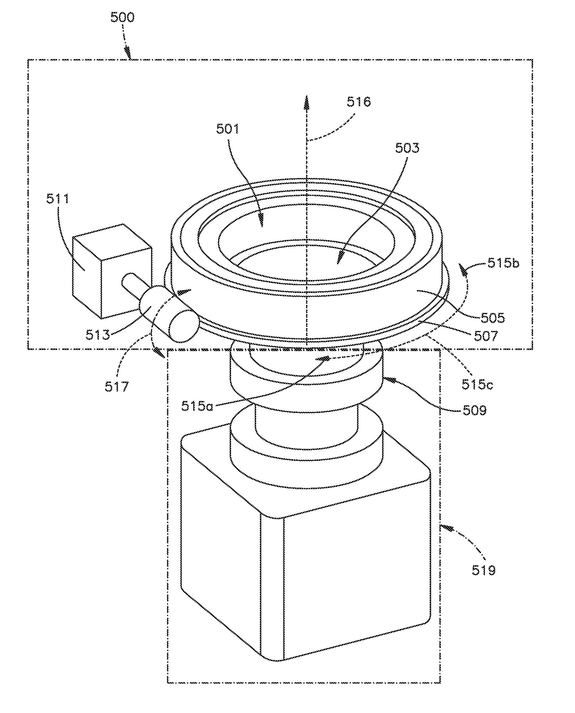
[0069]In the following, an automotive camera with the fixed aperture and an apparatus for light intensity adjustment is described. The apparatus can be used for controlling amount of light that reaches an image sensor, also denoted as imager of the camera. The apparatus comprises two polarizer filters, one of which may move with respect to another in such a way, that the amount of transmitted light is gradually changed. This allows keeping image sensor...


PUM


Abstract

An apparatus for light intensity adjustment mountable on an automotive camera includes at least one first linear polarizing filter, at least one second linear polarizing filter, the first linear polarizing filter and the second polarizing filter are arrangeable in front of a lens unit of an automotive camera such that incident light passes through the at least one first linear polarizing filter and the at least one second linear polarizing filter before entering the lens unit of the automotive camera, and at least one actuator for moving the at least one first linear polarizing filter and / or the at least one second linear polarizing filter with respect to each other such that the intensity of the emergent light is adjustable. The apparatus is characterized in enabling adjustment of the emergent light intensity by moving the first linear polarizing filter and / or the second linear polarizing filter with respect to each other.

Description

CROSS-REFERENCE TO RELATED APPLICATIONS[0001]This application claims priority to European Patent Application No. 14 178 462.9, filed in the European Patent Office on Jul. 25, 2014. This application is hereby incorporated by reference for all purposes in its entirety.BACKGROUND[0002]1. Field[0003]The present invention relates to an apparatus for light intensity adjustment mountable on an automotive camera, comprising at least one first linear polarizing filter, at least one second linear polarizing filter, the first linear polarizing filter and the second polarizing filter are arrangeable in front of a lens unit of an automotive camera such that incident light passes through the at least one first linear polarizing filter and the at least one second linear polarizing filter before entering the lens unit of the automotive camera, and at least one actuator for moving the at least one first linear polarizing filter and / or the at least one second linear polarizing filter with respect to ...

Claims


Application Information

Patent Timeline
Patent Type & Authority Applications(United States)
IPC IPC(8): B60R11/04H04N5/225
CPCB60R11/04H04N5/2256H04N5/2254H04N23/55H04N23/75H04N23/56
Inventor KONEVSKY, OLEGHOTTMANN, PHILIPP
Owner SMR PATENTS S A R L
Why Eureka
Try Eureka