Heat exchange system using an external rotor motor

Active Publication Date: 2016-04-07
ZHONGSHAN BROAD OCEAN
View PDF5 Cites 6 Cited by
  • Summary
  • Abstract
  • Description
  • Claims
  • Application Information

AI Technical Summary

Benefits of technology

[0028]1) the blower uses the external rotor axial fan, the rotor thereof features large rotational inertia, small fluctuation in torsion, and stable operation, and the wind blade is close to the exhaust outlet and has a low wind pressure coefficient, small wind resistance, and high efficiency, which causes the external rotor axial fan to blow large amount of wind from the exhaust outlet of the box and thus improving blowing effect; 2) the heat exchange system features high overall efficiency and low power consumption, and meets requirement of the current society for energy conservation and environmental protection; 3) the wind blade is an equal-width blade with a large area and in the vicinity of the exhaust outlet of the box, and thus greatly improving inducing capacity of the external rotor axial fan, and blowing effect of the heat exchange system; 4) the annular cylinder on the support is fit on a housing of the rotor of the external rotor motor, and the inner wall of the annular cylinder is interference fit with the outer wall of the rotor, which make the invention have simple assembling, reliable connection, high production efficiency, low processing difficulty, and reduced production cost; 5) the external rotor axial fan is combined and features simple installation and disassembly, and the external rotor motor and the wind blade can be transported separated, which reduces transportation cost; 6) by using the external rotor axial fan, overall volume of the heat exchange

Problems solved by technology

Problems with the system are: 1) rotational inertia of the drive motor 7 of the blower 2 is small, the wind blade 9 of the blow 2 is far away from the exhaust outlet 6, and thus having a high wind pressure coefficient, large wind resistance, and low efficiency, which causes the blower 2 to blow small amount of wind from the exhaust outlet 6 of the box 4, and thus an ideal blowing effect cannot be facilit

Method used


Image

  • Heat exchange system using an external rotor motor
  • Heat exchange system using an external rotor motor
  • Heat exchange system using an external rotor motor

Examples


Embodiment Construction

[0040]Further description of the invention will be given below in conjunction with specific embodiments and accompanying drawings.

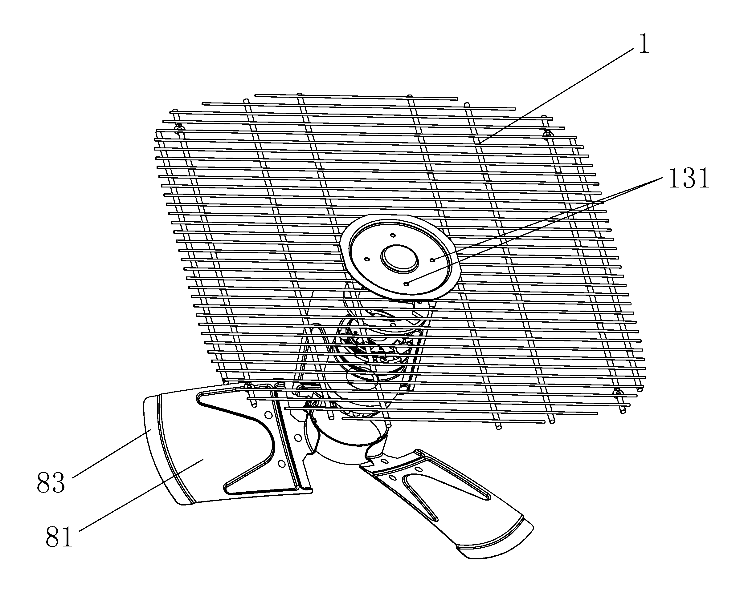
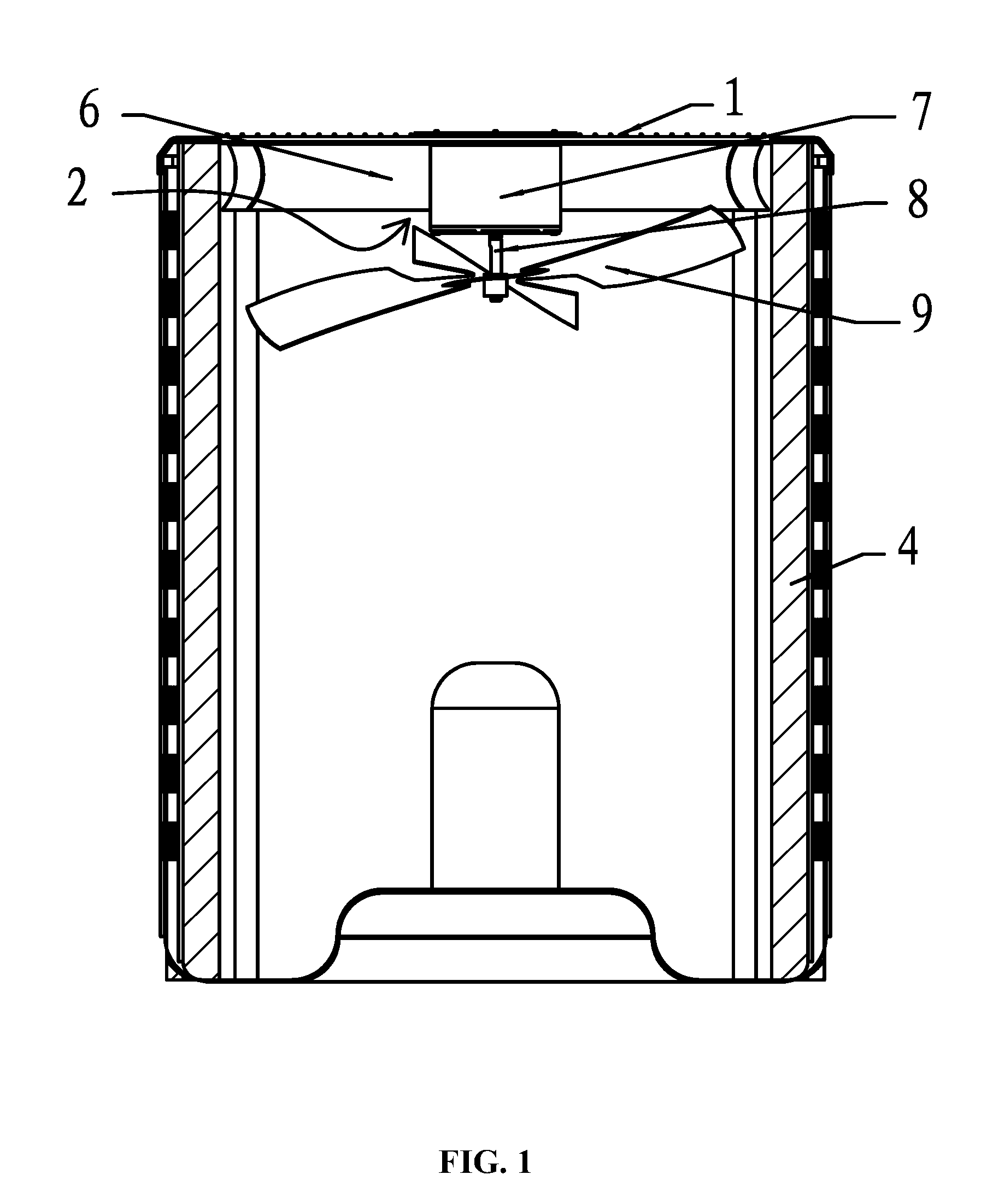
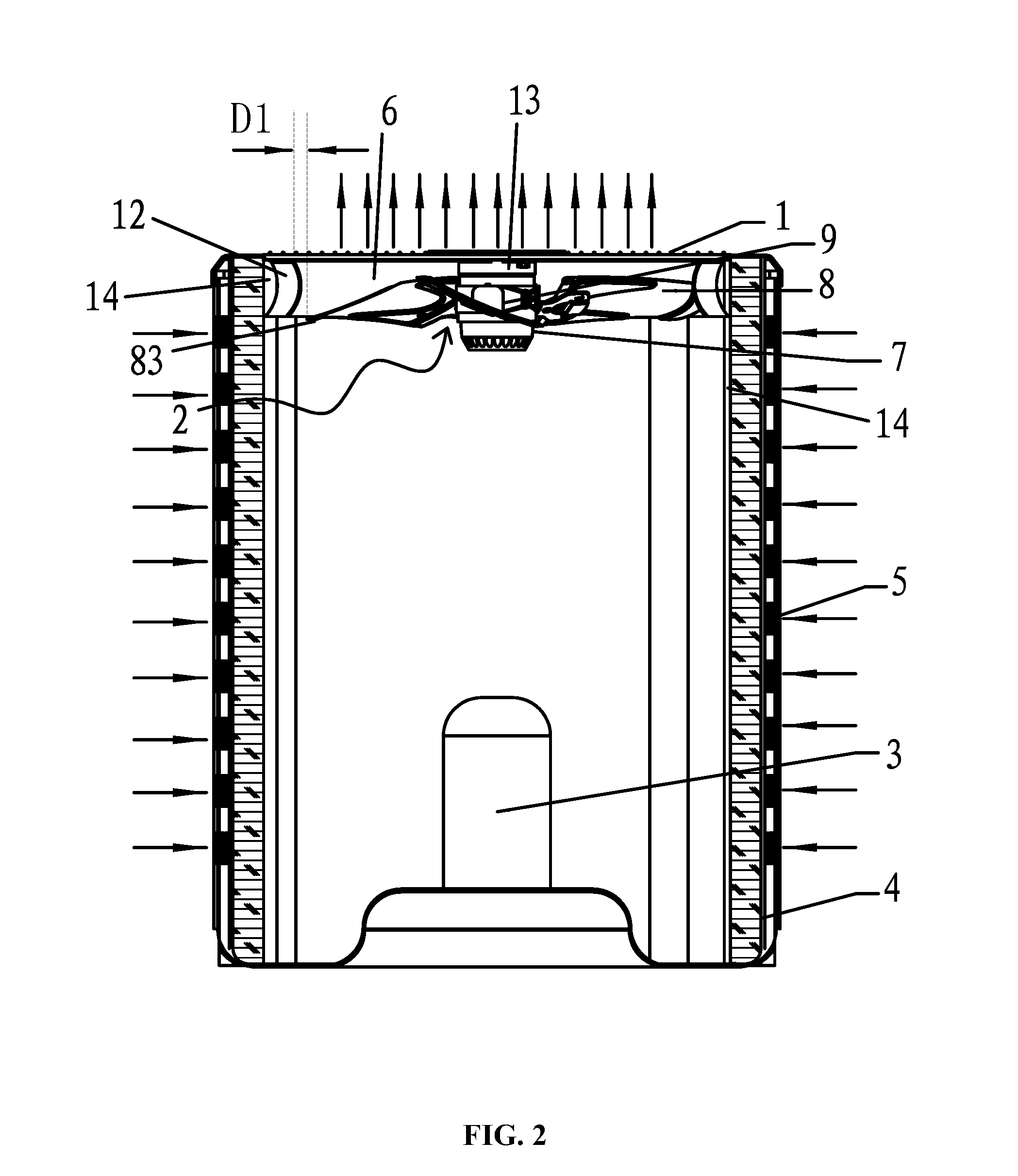
[0041]As shown in FIGS. 2-11, a heat exchange system of the invention comprises multiple grids 1, a blower 2, an inner side wall 14, a shock absorbing pad 13, a compressor 3, and a box 4 having multiple exhaust inlets 5 on the side thereof. The grid 1 is disposed at an exhaust outlet 6 of the box 4, the blower 2 is disposed in the box 4 and below the grid 1, and the compressor 3 is disposed on the bottom surface of the box 4. The blower 2 is an external rotor axial fan, and comprises an external rotor motor 7 and a wind blade 8, and the wind blade 8 is disposed outside a rotor 71 of the external rotor motor 7. The external rotor motor 7 comprises an axis, and the wind blade 8 comprises an outer surface 81, a top end 82, and a side end 83. The shock absorbing pad 13 is disposed between the multiple grids 1 and the external rotor motor 7.

[0042]The wind blad...


PUM


Abstract

A heat exchange system of the invention includes at least multiple grids, a blower including an external rotor motor and a wind blade, an inner side wall, a shock absorbing pad, a compressor, and a box having multiple exhaust inlets. The exhaust inlets are disposed on the side of the box. The grids are disposed at an exhaust outlet of the box. The blower is disposed in the box and below the grid. The compressor is disposed on a bottom surface in the box. The blower is an external rotor axial fan, and the wind blade is disposed outside a rotor of the external rotor motor. The shock absorbing pad is disposed between the grids and the external rotor motor.

Description

CROSS-REFERENCE TO RELATED APPLICATIONS[0001]This Application is a continuation-in-part of, and claims domestic priority benefits to U.S. patent application Ser. No. 12 / 876,147, filed Sep. 5, 2010, now pending. Pursuant to 35 U.S.C. §119 and the Paris Convention Treaty, U.S. patent application Ser. No. 12 / 876,147, filed Sep. 5, 2010, now pending, claims the benefit of Chinese Patent Application No. 200920236976.3 filed on Sep. 30, 2009. The contents of all of the aforementioned applications, including any intervening amendments thereto, are incorporated herein by reference in their entirety.CORRESPONDENCE ADDRESS[0002]Inquiries from the public to applicants or assignees concerning this document should be directed to: Matthias Scholl P.C., Attn.: Dr. Matthias Scholl Esq., 245 First Street, 18th Floor, Cambridge, Mass. 02142.BACKGROUND OF THE INVENTION[0003]1. Field of the Invention[0004]The invention relates to a heat exchange system.[0005]2. Description of the Related Art[0006]FIG. ...

Claims


Application Information

Patent Timeline
IPC IPC(8): F24F1/14F24F1/16F24F1/38
CPCF24F1/14F24F1/16F24F1/38F24F1/50F04D25/0613F04D29/668
Inventor WANG, XIONGCHENG
Owner ZHONGSHAN BROAD OCEAN
Why Eureka
Try Eureka