Heat Exchanger with Self-Retaining Bypass Seal

a heat exchanger and bypass seal technology, applied in the field of heat exchangers, can solve the problems of reducing the efficiency of the heat exchanger, difficult to provide a bypass seal, and gap between the heat exchanger core and the housing

Active Publication Date: 2016-04-07
DANA CANADA CORP
View PDF0 Cites 44 Cited by
  • Summary
  • Abstract
  • Description
  • Claims
  • Application Information

AI Technical Summary

Benefits of technology

[0018]In an embodiment, the seal is resilient and has an uncompressed thickness which is greater than said second gap. In an embodiment, the seal includes a plurality of legs having ends which engage the core in the second portion thereof. In an embodiment, the seal has a U-shape with t...

Problems solved by technology

Typically there are gaps between the heat exchanger core and the housing.
If left open, the gaps along the sides of the core will permit excessive bypass flow of the hot charge air, reducing the efficiency of the heat exchange...

Method used


Image

  • Heat Exchanger with Self-Retaining Bypass Seal
  • Heat Exchanger with Self-Retaining Bypass Seal
  • Heat Exchanger with Self-Retaining Bypass Seal

Examples


first embodiment

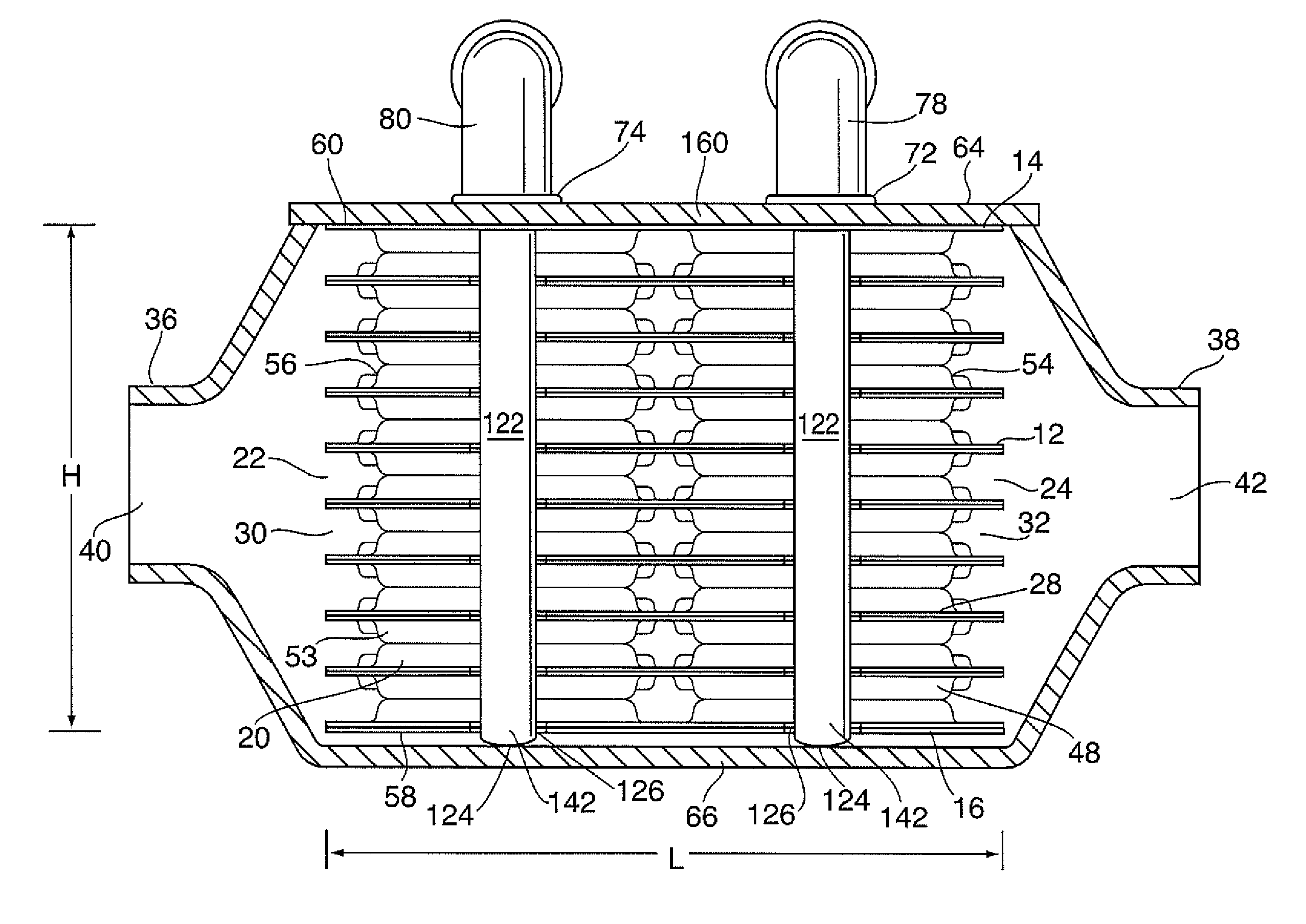
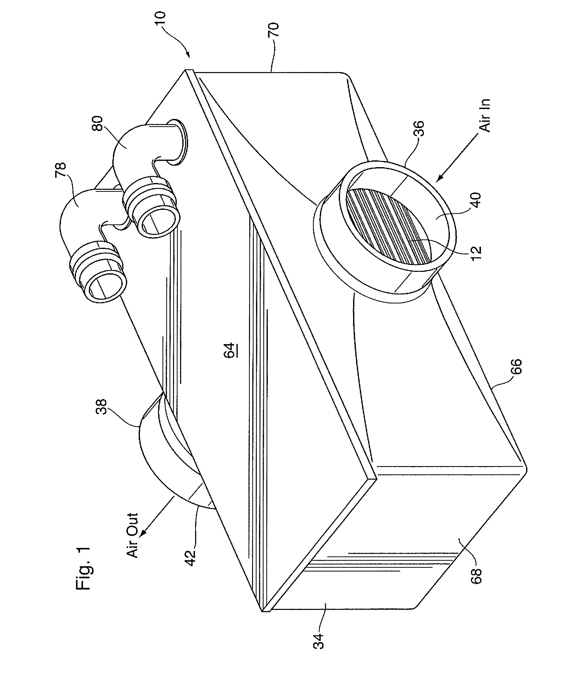
[0050]A heat exchanger 10 is now described below with reference to FIGS. 1 to 5C.

[0051]Heat exchanger 10 is a charge air cooler for a motor vehicle powered by an engine requiring compressed charge air, such as a turbocharged internal combustion engine or a fuel cell engine. The heat exchanger 10 may be mounted downstream of an air compressor and upstream of an air intake manifold of the engine to cool the hot, compressed charge air before it reaches the engine. However, in some embodiments the heat exchanger 10 may be integrated with the intake manifold, as further discussed below. In the following description, the coolant circulated through the heat exchanger 10 is a liquid coolant which may be the same as the engine coolant, and which may comprise water or a water / glycol mixture.

[0052]It will be appreciated that the specific arrangement and locations of the inlet and outlet openings for air and coolant will at least partially depend on the specific configuration of a vehicle's ai...

second embodiment

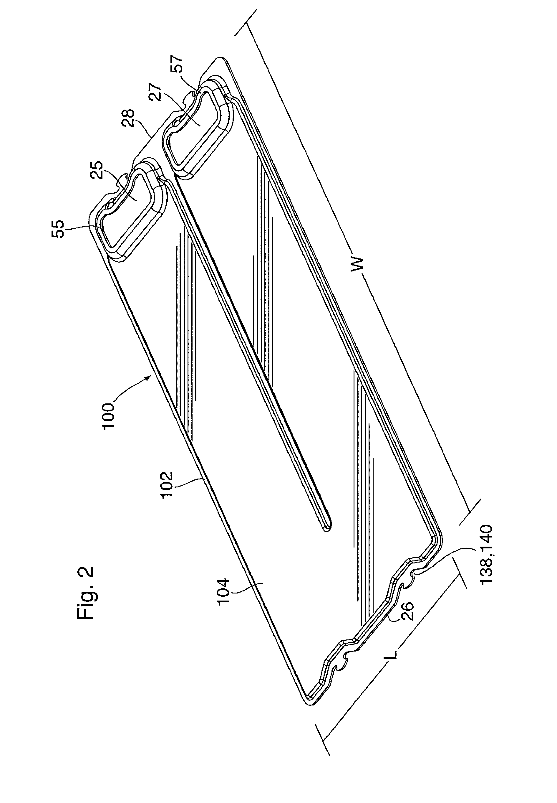
[0060]The corrugated fins 62 of the present embodiment are shown as a cross-hatched area in FIG. 5B. However, the corrugated fins of the present embodiment are the same as those of the second embodiment described below, comprising a plurality of parallel sidewalls 44 extending along the length L of core 12, wherein the sidewalls 44 have crests 46 at their tops and bottoms along which they are joined to each other and to adjacent flat tubes 48. The corrugated fins 62 as illustrated in FIGS. 10, 11, 17 and 18 correspond to the corrugated fins 62 of the present embodiment.

[0061]The corrugations defined by the corrugated fin 62 are open at the ends 22, 24 of core 12. Each of the side edges 63, 65 of the corrugated fin 62 is defined by one of the endmost sidewalls 44 of the corrugated fin 62.

[0062]It can be seen from FIG. 5B that one side edge 63 of each corrugated fin 62 is located at, and extends along, the first side 51 of one of the gas flow passages 52. The other side edge 65 of eac...

third embodiment

[0145]A heat exchanger 300 is now described below. Heat exchanger 300 includes a number of elements in common with heat exchangers 10 and 200 described above. These like elements are identified in the drawings and the following description with like reference numerals, and the description of these elements in connection with heat exchangers 10 and / or 200 applies equally to heat exchanger 300.

[0146]Heat exchanger 300 is similar in overall shape to heat exchanger 200 described above, the primary difference being that the inlet and outlet manifolds 54, 56 of heat exchanger 300 are centrally located within the core 12 and aligned along the length L thereof, dividing each gas flow passage 52 into two segments 52a, 52b and also dividing each corrugated fin 62 into two segments 62a, 62b.

[0147]As with heat exchanger 200 described above, heat exchanger 300 includes a housing 34 having a top cover 64 which is integrated with the core 12. The top cover 64 comprises a relatively thick, flat f...


PUM


Abstract

A gas/liquid heat exchanger comprises a stack of flat tubes, defining liquid flow passages. Spaces between the flat tubes define gas flow passages, with the sides of the core having an irregular comb-like arrangement. The heat exchanger further comprises a housing having side covers over the sides of the core, and being spaced from the sides of the core. The core has at least one portion of reduced width, so as to provide channels extending throughout the height of the core. The heat exchanger further comprises a pair of side seals at least partly received in the gap between the side cover of the housing and the core, and more particularly in the channels along the sides of the core. The side seal extends throughout the height of the core and has a thickness which is greater than that of the gap.

Description

CROSS-REFERENCE TO RELATED APPLICATION[0001]This application claims priority to and the benefit of U.S. Provisional Patent Application No. 62 / 059,265 filed Oct. 3, 2014, the contents of which are incorporated herein by reference.FIELD OF THE INVENTION[0002]The invention generally relates to heat exchangers for cooling a hot gas with a liquid coolant, and particularly to gas-liquid charge air coolers having a housing enclosing a heat exchanger core.BACKGROUND OF THE INVENTION[0003]It is known to use gas-liquid heat exchangers to cool compressed charge air in turbocharged internal combustion engines or in fuel cell engines, or to cool hot engine exhaust gases. For example, compressed charge air is typically produced by compressing ambient air. During compression, the air can be heated to a temperature of about 200° C. or higher, and must be cooled before it reaches the engine.[0004]Various constructions of gas-cooling heat exchangers are known. For example, gas-cooling heat exchangers...

Claims


Application Information

Patent Timeline
IPC IPC(8): F28D1/02F28F1/04F28F1/12F28D1/053
CPCF28D1/0233F28F1/128F28F1/045F28D1/05366F28F2280/06F02B29/0462F28F3/025F28F9/005F28F9/26F28D9/0056F28F2009/029F28D2021/0082Y02T10/12
Inventor STEWART, NIKOLAS S.SHORE, COLIN A.KINDER, LEE M.
Owner DANA CANADA CORP
Why Eureka
Try Eureka