Managed access system for traffic flow optimization

a traffic flow and access system technology, applied in the direction of navigation instruments, instruments, analogue processes for specific applications, etc., can solve the problems of increasing increasing the total flow, and increasing the number of vehicles, so as to maximize (or improve) the road capacity, the effect of minimizing the speed of individual vehicles

Active Publication Date: 2016-04-07
HANNAH MARC R
View PDF17 Cites 55 Cited by
  • Summary
  • Abstract
  • Description
  • Claims
  • Application Information

AI Technical Summary

Benefits of technology

[0013]The present disclosure generally relates to methods and systems to manage vehicle traffic density on one or more roads in a transportation system by controlling road access via one or more of: permissions, tolls, fees, and penalties. Control can be managed in real-time based upon demand, and permissions and fees are in one embodiment specific to individual vehicles requesting access. Centralized software algorithms can manage access permissions in a way, in one embodiment, that prevents excessive traffic demand from reducing traffic flows below optimum levels, thereby maximizing (or at least improving) road capacity and minimizing (or at least improving) travel times.

Problems solved by technology

This results in significant additional costs in fuel, personal time, business productivity, and pollution.
Past the peak, adding more vehicles becomes counterproductive, reducing both total flow and individual vehicle speeds.
A disadvantage of existing cost-driven methods, however, is that they place an uneven burden on the driving population based upon financial status.
In this sense, they are not income neutral or fair.
Also, because of this affordability constraint, their demand reduction effects help, but often fall far short of what would be necessary to maximize traffic flow efficiencies in highly oversaturated road systems.

Method used


Image

  • Managed access system for traffic flow optimization
  • Managed access system for traffic flow optimization
  • Managed access system for traffic flow optimization

Examples


implementation example

Overview

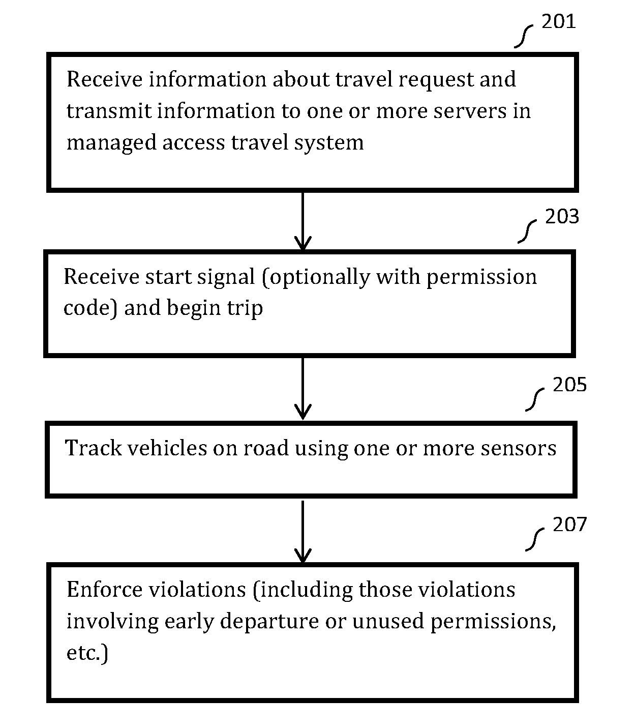
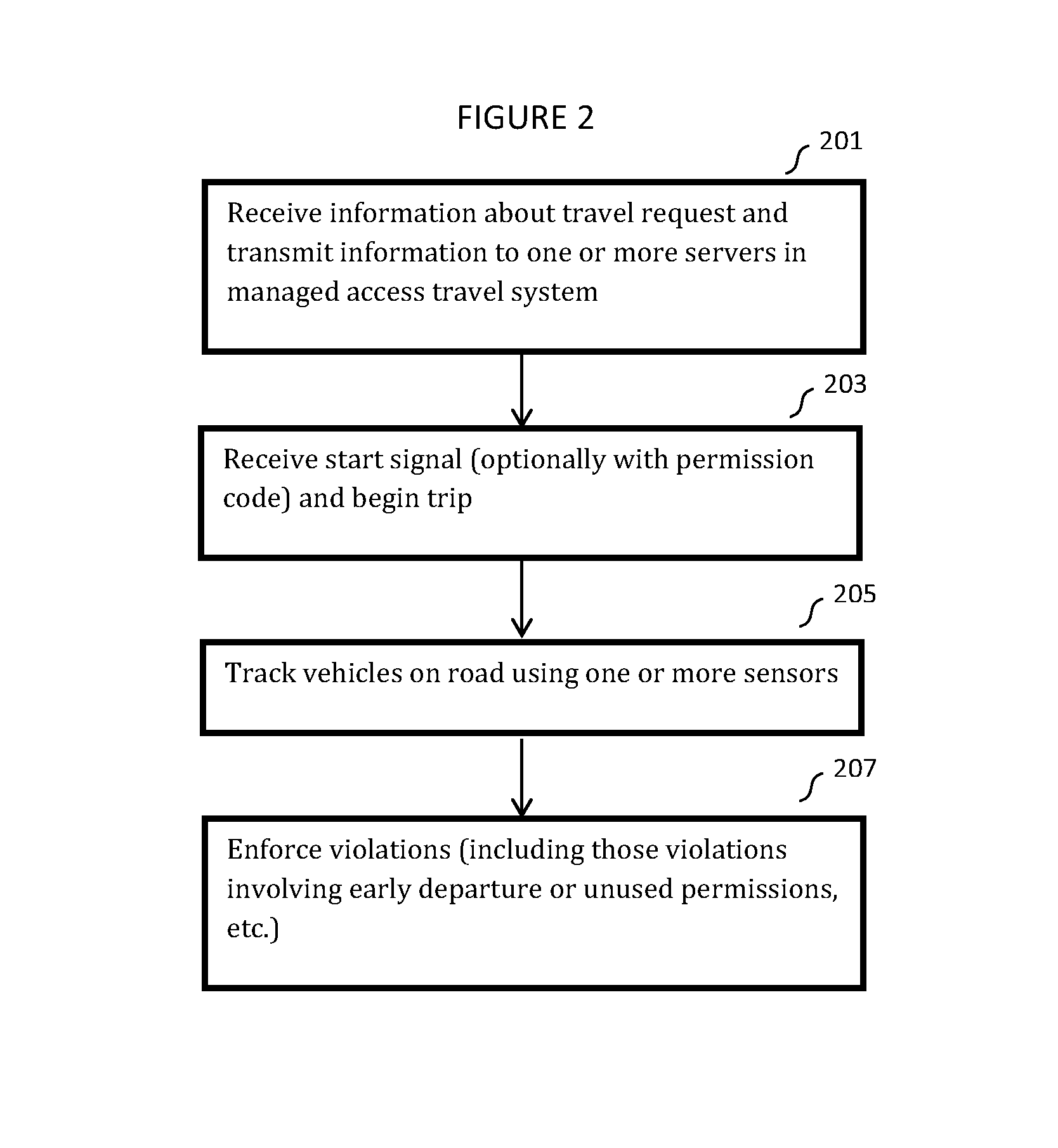
[0040]In one possible embodiment, which will be subsequently referred to as MATS (Managed Access Traffic System), anyone wanting to drive somewhere would first request road access permission from central MATS servers via any one of many possible ways, including a phone call, text message, smartphone app, web page or dedicated electronic device. Additional information such as where they are and where they want to go may accompany the request. The MATS server would quickly respond, either granting permission to immediately leave, or giving a position in a virtual departure queue and perhaps a countdown timer showing approximately how much wait time is left. Once the front of the virtual queue is reached, the requesting driver is signaled, permission to depart is granted and their journey can begin. The basic user interaction can be as simple as that. It's also possible for part or all of the road access request / grant protocol be automatically performed by a device that knows w...

hardware example b

Low Cost Per Vehicle, Adding Privacy

[0091]This example, shown in FIG. 8, adds a toll transponder containing a Bluetooth wireless interface to communicate with a key fob. The key fob contains a long range texting radio, as in Example A (FIG. 7), but with a Bluetooth interface added for communication to the vehicle mounted toll transponder. This combination provides sufficient hardware and battery size in the transponder to use transmitted permission codes with a salted hash of the license number for enforcement identifiers, thus allowing increased privacy safeguards. The permission code could be received from the MATS server by the key fob while away from the vehicle. Just prior to departure, the key fob transfers the permission code and salt value via Bluetooth to the toll transponder, which can be mounted near the front windshield of the vehicle. Road mounted enforcement sensors would contain cameras with license number recognition and RFID reader to poll the permission codes and s...

example c

Hardware Example C

Medium Cost Per Vehicle, Adding Crowd-Based Enforcement

[0093]In this example, shown in FIG. 9, the key fob is a Bluetooth device that is simply a button and display peripheral for a smartphone application. The smartphone itself may already be owned by the driver, or a very low cost smartphone could be provided to support the MATS protocols. A device can be mounted to the front of the vehicle, for example, as a smart license plate frame (or as a smart license plate). The license plate frame is a convenient mounting point since it's generally standardized, and concealed routing of power to the device from under the hood is relatively straightforward. An alternative to routing power from under the hood would be to use a small wind turbine generator and battery to take advantage of the wind that is always available when the vehicle is moving. This smart plate frame would provide a control processor a GPS receiver, a radio frequency (RF) transceiver to transmit and rece...


PUM


Abstract

The present disclosure relates to methods and systems to manage traffic density in a transportation system, and by doing so, maintain, in one embodiment, traffic flows near optimum levels to maximize road capacity and minimize travel times. The method includes, in one embodiment, a mechanism for vehicles to request road access from a centalized control, a queuing system that allows road access to be granted to individual vehicles over an extended period of time in a fair and organized fashion, a measurement system that allows traffic flow and density throughout the system to be determined in real-time, and an enforcement and fraud prevention mechanism to ensure that the rules and permissions imposed by the system are followed.

Description

[0001]This application claims the benefit of U.S. Provisional Patent Application No. 62 / 060,511, filed Oct. 6, 2014, and this provisional patent application is hereby incorporated herein by reference.BACKGROUND[0002]In many major cities around the world, trip durations during peak traffic hours can be 5 to 10 times what they are in uncontested traffic. This results in significant additional costs in fuel, personal time, business productivity, and pollution. Congestion relief measures often take one of three forms:[0003]1) increase system capacity by building more roads,[0004]2) improve flows by adjusting signal timing, entry / exit controls, etc., or[0005]3) improve flows by reducing the number of vehicles in any given region, road, or lane.[0006]The focus of the present disclosure is method 3—to increase flows by reducing the number of vehicles on the road (vehicle density). To understand the advantages of reducing vehicle density it's useful to look at the general relationship betwe...

Claims


Application Information

Patent Timeline
Patent Type & Authority Applications(United States)
IPC IPC(8): G01C21/34H04W4/80
CPCG01C21/3415G08G1/0116G08G1/0133G08G1/0145G08G1/017G08G1/09G08G1/012G08G1/0129G08G1/0175G08G1/04G08G1/092G08G1/093G08G1/096716G08G1/096741G08G1/096775G08G1/096783G08G1/202G08G1/207G06V20/54H04W4/80
Inventor HANNAH, MARC R.
Owner HANNAH MARC R
Why Eureka
Try Eureka