Ceramic device and piezoelectric device

a ceramic device and piezoelectric technology, applied in the field of ceramic devices, can solve the problems of adverse effects on the “voltage-displacement characteristics” of the piezoelectric device as a whole, electrical short circuits of the surface electrode pair, and electrical short circuits of the pair of surface electrodes, so as to increase the reliability of electrical connections, adhesion and bonding of the conductive joining material, the effect of high wettability

Active Publication Date: 2016-04-07
NGK INSULATORS LTD
View PDF4 Cites 12 Cited by
  • Summary
  • Abstract
  • Description
  • Claims
  • Application Information

AI Technical Summary

Benefits of technology

[0009]According to (Characteristic 1) described above, the surface of the side electrode is comprised only of the material (typically, platinum) for the side electrode having relatively high wettability to the conductive joining material (typically, solder), and thus the conductive joining material is likely to wet on the surface of the side electrode. Thus, when the side electrode is joined and secured to a substrate with the conductive joining material as described above, for example, adhesion and bondability of the conductive joining material to the side electrode increase, leading to an increase in reliability concerning electrical connection between the conductive joining material and the substrate.
[0010]According to (Characteristic 2) described above, when the side electrode is joined and secured to the substrate with the conductive joining material as described above, the conductive joining material is less likely to ride over an upper end surface of the side electrode, and enter the surface (an upper surface) of the surface electrode due to the presence of the protrusion.
[0011]According to (Characteristic 3) described above, if the conductive joining material rides over the upper end surface of the side electrode, and further rides over the protrusion to enter the “inner region” on the surface of the surface electrode, expansion of a range of wetting of the conductive joining material in the “inner region” can be suppressed by the presence of the “exposed portions” having lower wettability to the conductive joining material. As a result, the extent to which expansion and contraction of the surface electrode are restricted at application of voltage to the piezoelectric device can be suppressed, and the adverse effects on the “voltage-displacement characteristics” of the piezoelectric device as a whole can be suppressed.

Problems solved by technology

If such an event occurs, expansion and contraction of the surface electrodes 210 can be restricted at application of voltage to the piezoelectric device due to adherence of the solder to the surfaces of the surface electrodes 210, and this can adversely affect “voltage-displacement characteristics” of the piezoelectric device as a whole.
Furthermore, if an excessive amount of solder enters the surfaces of the surface electrodes 210, the solder can enter a gap between the pair of surface electrodes 210, resulting in electrical short circuits of the pair of surface electrodes 210.
As described above, the state of the solder riding over the upper end surfaces of the side electrodes and entering the surfaces of the surface electrodes is not preferred because it leads to the adverse effects on the “voltage-displacement characteristics” of the piezoelectric device.

Method used


Image

  • Ceramic device and piezoelectric device
  • Ceramic device and piezoelectric device
  • Ceramic device and piezoelectric device

Examples


Embodiment Construction

[0042]An embodiment of a piezoelectric device according to the present invention is described below with reference to the drawings.

[0043](Structure)

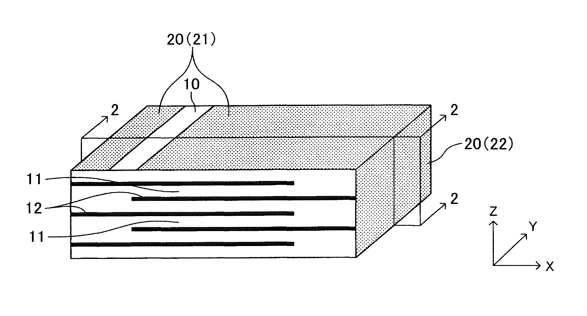
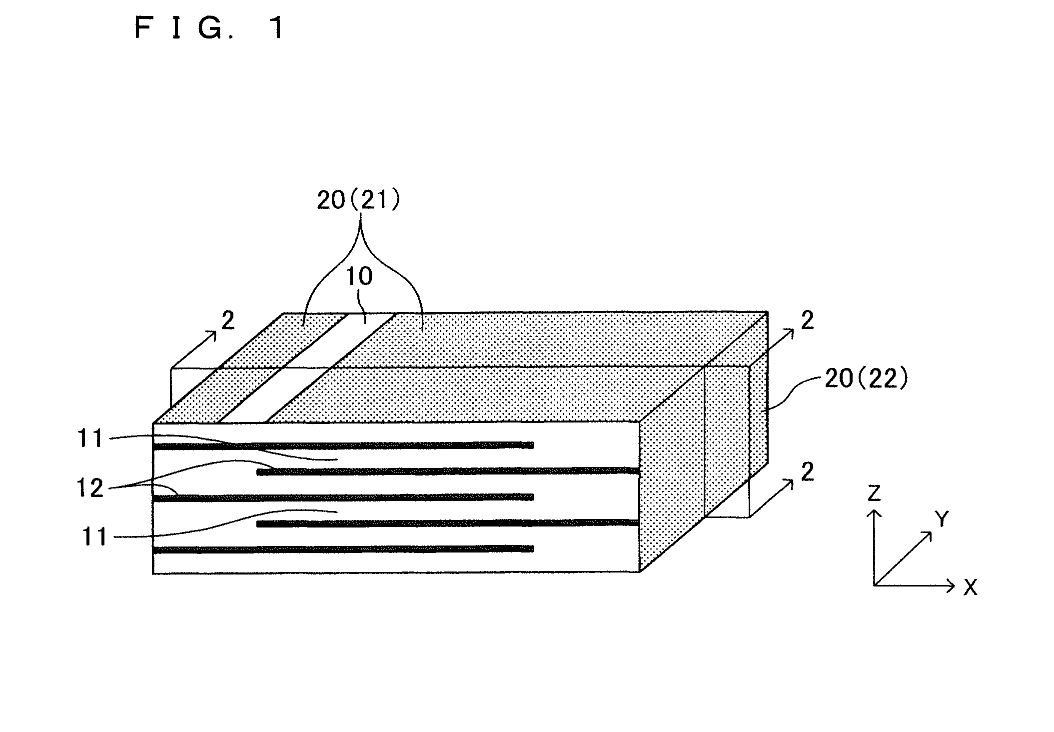
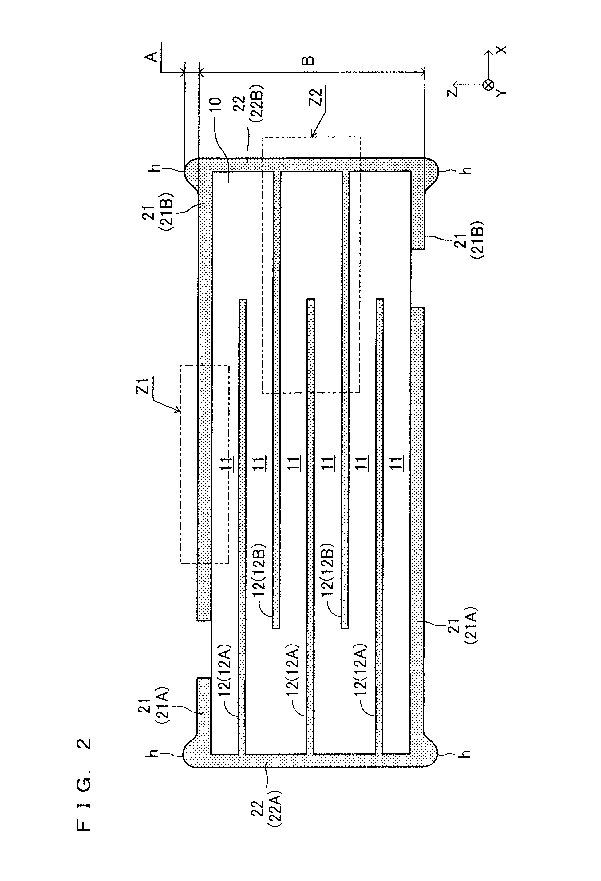
[0044]As illustrated in FIG. 1 and FIG. 2, which is a cross sectional view taken along the line 2-2 of FIG. 1, a piezoelectric device according to the present embodiment is a fired body, and includes a rectangular parallelepiped body part 10 and an external electrode 20 provided on the body part 10 to cover at least part of a surface of the body part 10.

[0045]The body part 10 includes a plurality of (six in this example) piezoelectric layers 11 comprised of a piezoelectric material and a plurality of (five in this example) layered internal electrodes 12, and is a stack of alternating piezoelectric layers 11 and internal electrodes 12 having the piezoelectric layers 11 as an uppermost layer and a lowermost layer. The piezoelectric layers 11 and the internal electrodes 12 are stacked in parallel to each other. As for the size (after firing...


PUM

PropertyMeasurementUnit
equivalent diameteraaaaaaaaaa
heightaaaaaaaaaa
heightaaaaaaaaaa

Abstract

A piezoelectric device is a fired body including a body part 10 and external electrodes 21 and 22. A surface of the side electrode 22 is comprised only of a material for the side electrode 22. On a surface of the surface electrode 21 or a surface of a connection portion where the surface electrode 21 and the side electrode 22 are connected to each other, a protrusion h extending along a direction along which the connection portion extends and sticking out in a thickness direction of the surface electrode 21 is provided. A region, on the surface of the surface electrode 21, farther from the connection portion than the protrusion h is interspersed with a plurality of exposed portions in each of which a surface of a ceramic material having lower solder wettability than a material for the surface electrode 21 is exposed.

Description

TECHNICAL FIELD[0001]The present invention relates to ceramic devices and, in particular, to a piezoelectric device. The piezoelectric device is also referred to as a piezoelectric / electrostrictive device.BACKGROUND ART[0002]As an example of this type of piezoelectric device, WO 2012 / 132661 discloses a piezoelectric device that is a fired body including a body part 100 and an external electrode 200 as illustrated in FIG. 22. In the piezoelectric device illustrated in FIG. 22, the body part 100 is a stack of alternating piezoelectric layers 110 and internal electrodes 120. The external electrode 200 includes a pair of surface electrodes 210 covering parts of an upper surface of the body part 100, and a pair of side electrodes 220 covering at least parts of respective side surfaces of the body part 100 and being connected to the internal electrodes 120 and the surface electrodes 210 at respective sides.[0003]This type of piezoelectric device has actively been developed as an element (...

Claims


Application Information

Patent Timeline
Patent Type & Authority Applications(United States)
IPC IPC(8): H01L41/047H01L41/083
CPCH01L41/083H01L41/0472H01L41/0477H10N30/872H10N30/877H10N30/50H10N30/053
Inventor UETANI, MASAYUKIKOIZUMI, TAKAAKIMASUDA, IZUMIKAKU, TAKESHI
Owner NGK INSULATORS LTD
Why Eureka
Try Eureka