
Product display case or hot plate display case having an edge-mounted LED array for illuminating a light pipe for illuminating the interior portion of the product display case or hot plate display case, and/or an edge mounted LED array for illuminating a glass shelf within the product display case or hot plate display case

a technology of led arrays and light pipes, which is applied in the direction of furniture parts, lighting and heating equipment, instruments, etc., can solve the problems of not being desirable as light sources for present day use, affecting the service life of each one of these well-known light sources, and not being energy-efficient, etc., to achieve the effect of effectively illuminated glass plates, and not adversely affecting the service life of leds

Inactive Publication Date: 2016-04-14
A J ANTUNES & CO
View PDF7 Cites 79 Cited by
  • Summary
  • Abstract
  • Description
  • Claims
  • Application Information

AI Technical Summary

Benefits of technology

The present invention provides a product display case with a linear array of LEDs that illuminates the interior of the case through a glass plate using total internal reflection principles. The LEDs may be mounted on a metal frame or bracket structure, and the glass plate is mounted within an open-to-the-ambient atmosphere heated product display case. A cooling fan may be associated with the LEDs to maintain a cooler environment. Alternatively, the LEDs may be mounted on a glass shelf that illuminates the entire shelf using total internal reflection principles. The patent aims to provide a more energy-efficient and cost-effective method of illuminating product display cases.

Problems solved by technology

Although each one of these conventional light sources has obviously worked satisfactorily, is well-known, and have been in widespread use for many years, they are not truly desirable as light sources for present day usage for a variety of reasons.
For example, none of these well-known light sources are energy efficient.
In addition, the service life of each one of such conventional light sources is relatively short, thereby requiring replacement by service personnel.
Incan-descent lights usually last for only 750-1200 hours, and are notoriously energy inefficient, effectively converting only approximately 5% of their energy into visible light.
Fluorescent lights require the use of electrical ballasts for controlling or regulating the current flowing through the lights, and they also contain mercury, rendering them hazardous and requiring careful handling and disposal.
They also only have a service life of only approximately 10,000 hours.
Halogen or quartz lamps are relatively expensive, their costs resulting in expenditures which can be approximately four times that of a comparable incandescent bulb.
In addition, quartz lamps are delicate and can be easily damaged.
Special or careful handling of such lamps is therefore required, and still further, care must be taken not to permit oils from human skin to contaminate surface portions of quartz lamps in view of the fact that such contamination can lead to premature failure of the lamps.
One caveat to be aware of in connection with the usage of LED lights or lamps, however, resides in the fact that LED lights or lamps can only operate effectively within an ambient temperature range of, for example, approximately 40° F. to 130° F. Operation of LED lights or lamps with-in temperature environments of, for example, higher than 140° F. can lead to failure of the lights or lamps.
However, if LED lights or lamps are to be utilized within heated product display cases, wherein the ambient temperatures are normally within the range of, for example, 165° to 180° F., such ambient environments could present operational drawbacks with respect to the utilization of LED lights or lamps within such environments.

Method used


Image

  • Product display case or hot plate display case having an edge-mounted LED array for illuminating a light pipe for illuminating the interior portion of the product display case or hot plate display case, and/or an edge mounted LED array for illuminating a glass shelf within the product display case or hot plate display case
  • Product display case or hot plate display case having an edge-mounted LED array for illuminating a light pipe for illuminating the interior portion of the product display case or hot plate display case, and/or an edge mounted LED array for illuminating a glass shelf within the product display case or hot plate display case
  • Product display case or hot plate display case having an edge-mounted LED array for illuminating a light pipe for illuminating the interior portion of the product display case or hot plate display case, and/or an edge mounted LED array for illuminating a glass shelf within the product display case or hot plate display case

Examples


Embodiment Construction

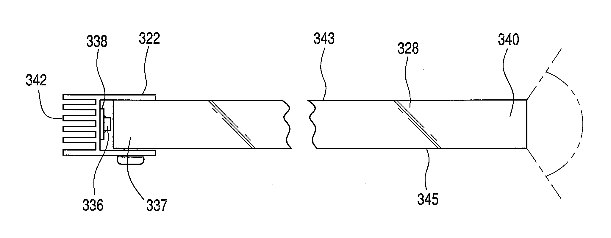
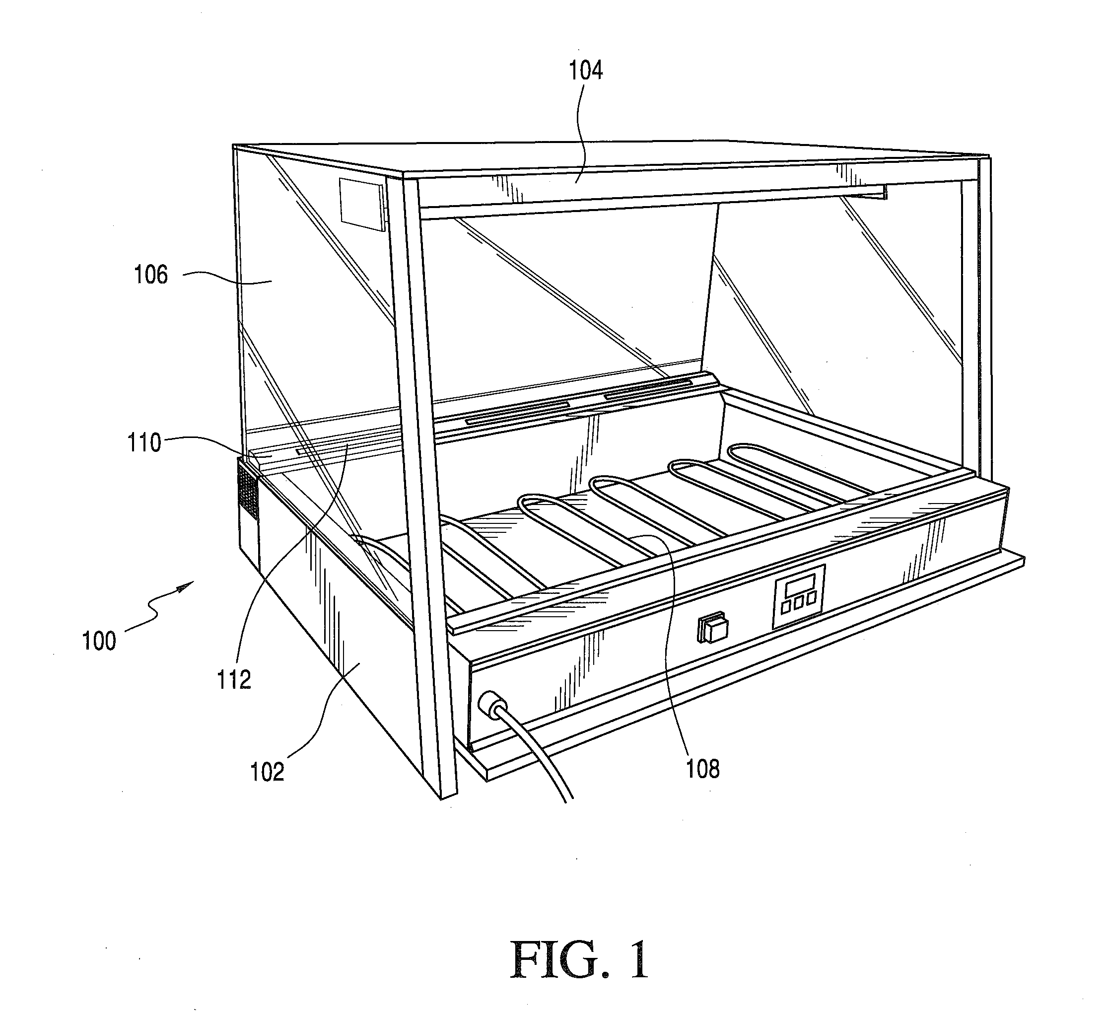
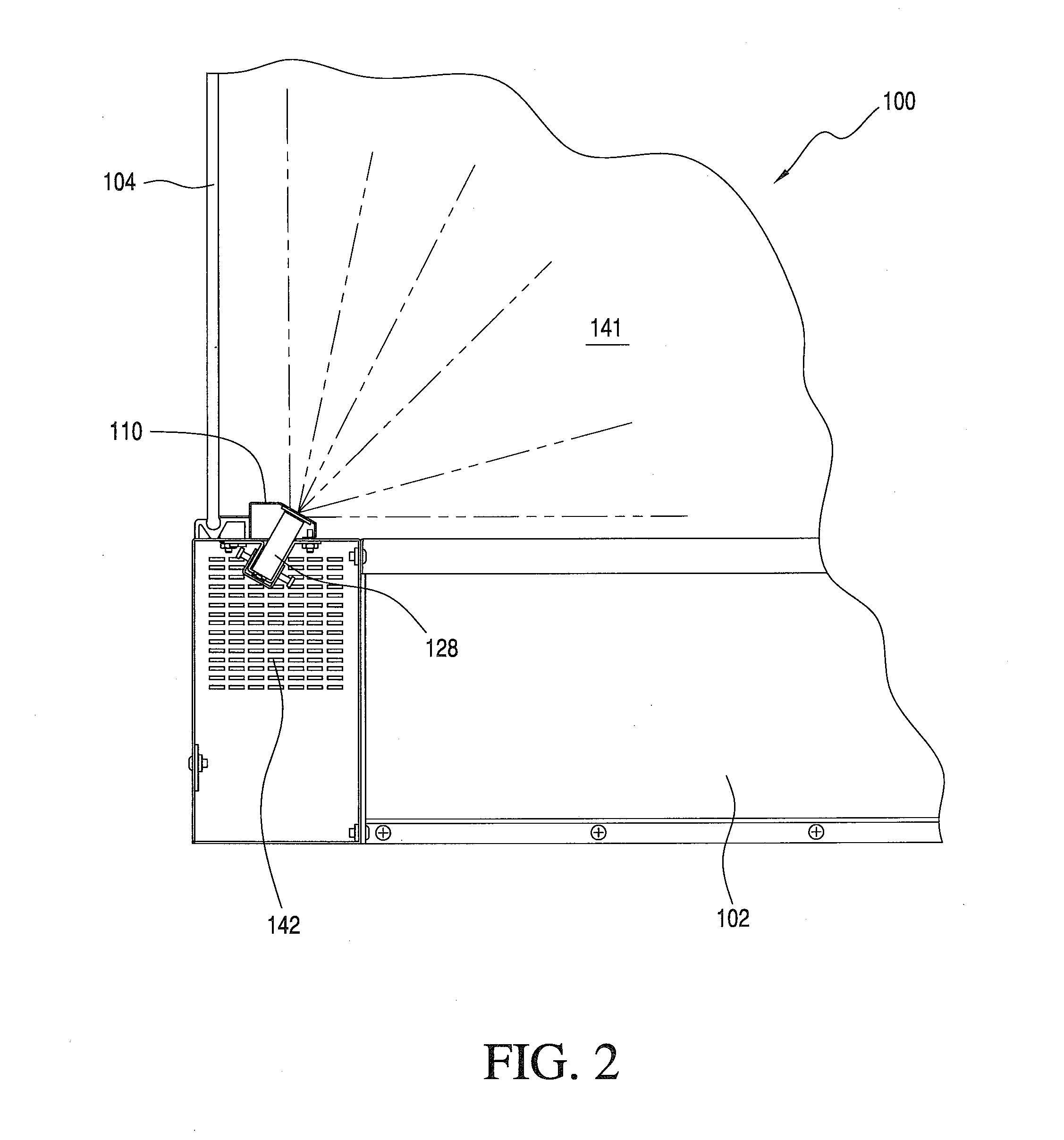
[0018]Referring now to the drawings, and more particularly to FIG. 1 thereof, there is shown a heated product display case, such as, for example, a product display case that would normally be employed within a commercial bakery or similar establishment for displaying muffins, breads, pastries, and the like, wherein the heated product display case is generally designated by means of the reference character 100. It is seen that the product display case 100 is conventionally constructed so as to comprise a metal frame base unit 102, and peripheral metal framework members 104 fixedly secured to the metal frame base unit 102 so as to support and secure therewithin suitable panes of glass 106 or other transparent material members through which customers or consumers can view the displayed products. It is also seen that suitable heating structure, in the form of heating coils 108, are mounted within the metal frame base unit 102 of the product display case 100, so as to provide the product...


PUM


Abstract

The present invention comprises a linear array of LEDs which can be utilized in conjunction with a product display case wherein the linear array of LEDs is operatively mounted upon, and disposed immediately adjacent to, a first end edge portion of a glass plate so as to effectively illuminate the glass plate by means of total internal reflection principles whereby the glass plate operatively serves as a light pipe such that the light emitted from a second opposite end edge portion of the glass light pipe can illuminate the interior portion of the product display case. Alternatively, the linear array of LED lights can be operatively mounted upon, and disposed immediately adjacent to, an edge portion of a glass shelf disposed within the product display case so as to likewise illuminate the glass shelf itself by means of total internal reflection principles whereby the illumination from the glass shelf serves to illuminate the products being displayed.

Description

STATEMENT REGARDING FEDERALLY SPONSORED RESEARCH OR DEVELOPMENT[0001]Not ApplicableNAMES OF PARTIES TO JOINT RESEARCH AGREEMENT[0002]Not ApplicableINCORPORATION BY REFERENCE OF MATERIAL SUBMITTED ON A COMPACT DISC[0003]Not ApplicableFIELD OF THE INVENTION[0004]The present invention relates generally to product display cases, more particularly to LED-illuminated light pipes, and even more particularly to an array of LEDs which can be utilized in conjunction with a product display case wherein the LED array is operatively mounted upon or disposed immediately adjacent to a first edge portion of a glass plate so as to effectively illuminate the glass plate, by means of total internal reflection principles, whereby the glass plate operatively serves as a light pipe such that the light emitted from a second opposite edge portion of the glass light pipe can illuminate the interior portion of the product display case. Alternatively, the array of LED lights can be operatively mounted upon or...

Claims


Application Information

Patent Timeline
IPC IPC(8): A47F3/00F21V8/00
CPCA47F3/001G02B6/0085G02B6/0073G02B6/0095A47B2220/0077A47F3/007A47F11/10G02B6/0068G02B6/0091
Inventor CLARK, JOSEPH R.MILA, TED R.
Owner A J ANTUNES & CO
Learn More