
Bone Implants

a bone implant and bone technology, applied in the field of bone implants, can solve the problems of limiting affecting the ease and/or rapidity of implantation, and affecting the growth rate of bone,

Active Publication Date: 2016-04-14
LDR MEDICAL
View PDF1 Cites 43 Cited by
  • Summary
  • Abstract
  • Description
  • Claims
  • Application Information

AI Technical Summary

Benefits of technology

The present disclosure describes an implant, an instrument for implantation and a method for manufacturing the implant. The implant has a longitudinally elongated body with a longitudinal internal conduit that is obtained through a combination of central and transverse machining operations. The internal conduit is in communication with the outside of the body through windows while preserving the turns and the wall of the body behind the turns. The technical effect of this design is that it provides a secure and reliable implant with improved injection and aspiration capabilities.

Problems solved by technology

A problem in the field of implants relates to bone growth and notably arthrodesis, i.e. the bone merging of two structures, such as for example vertebrae.
A problem in the field relates to the solidity since it is desirable to guarantee the integrity of the implant in spite of its small size and its often recessed layout.
A problem relating to implants in general, in particular spinal implants and notably facet implants, relates to the stability of the implant.
Another general problem relates to the ease and / or the rapidity of the implantation.
Intra-facet implants, often accompanied by other problems such that, for example, the requirement of providing the graft or bone substitute or cement for facilitating the merging, for example by means of the presence of a grafting chamber in the implant, in spite of its small size, and by maintaining sufficient rigidity of the implant in order to support the forces between both fixed facets.
Transfacet implants, which often provide the advantages of being simple, being able to be used percutaneously and allowing compression of articular facets against each other, are often accompanied by other problems such as for example, the lack of sharpening, cleaning or tapping of the articular joints, which limits the bone growth rate.
The diversity of the problems, notably of those discussed above, is generally accompanied by the problem that a same implant cannot be equally used as a transfacet implant and as an interfacet implant, which forces the provision of various types of implants and instruments.

Method used


Image

  • Bone Implants
  • Bone Implants
  • Bone Implants

Examples


Embodiment Construction

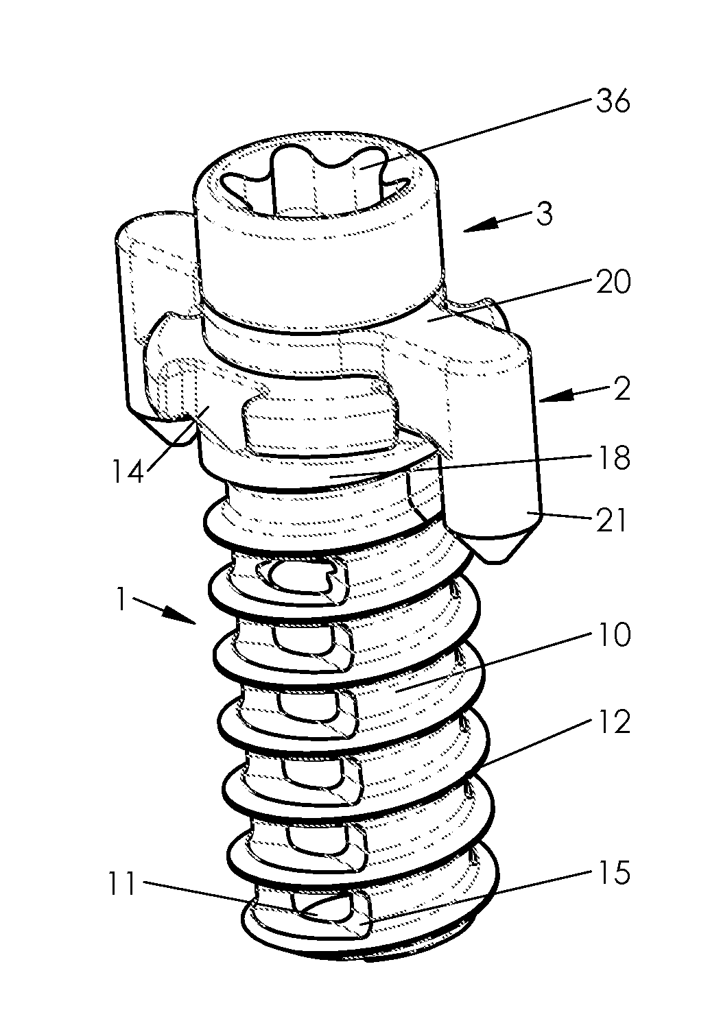
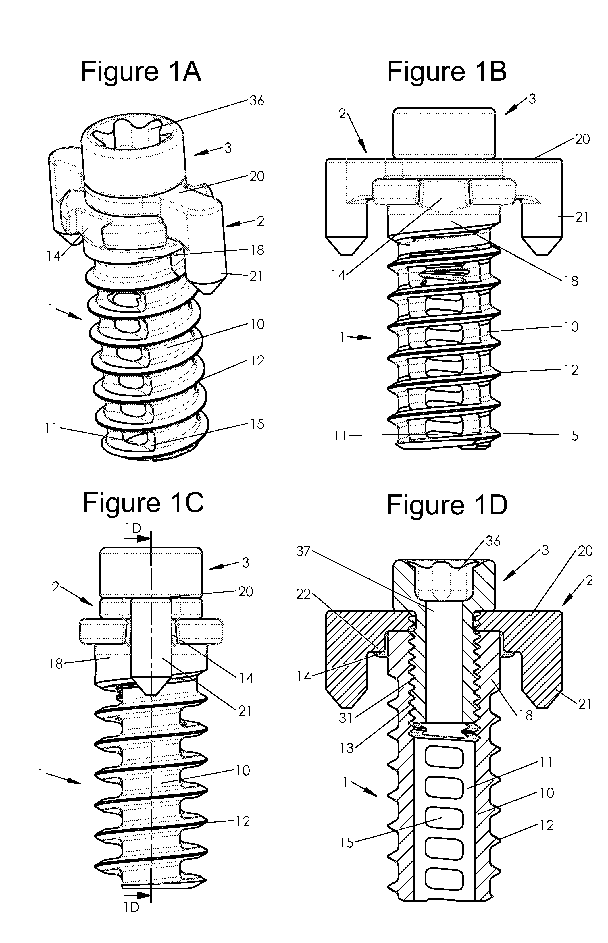
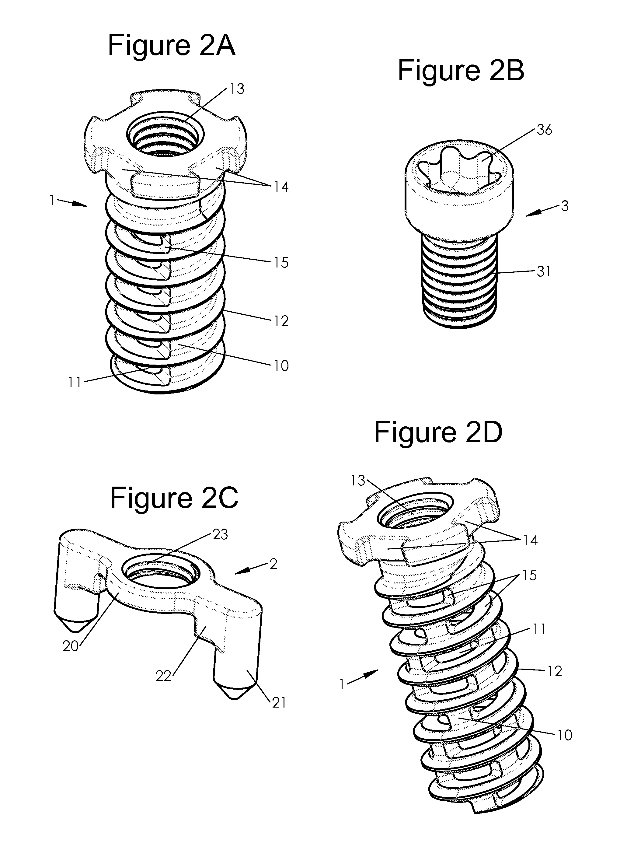
[0040]The present disclosure relates to various embodiments of bone implants and of instruments for implanting such implants. As mentioned in the preamble of the present application, various embodiments may relate in particular to spinal implants, for example for arthrodesis of two vertebral structures. The present application more particularly details spinal implants, notably so-called “facet” implants, intended to be implanted between the articular facets of the vertebrae (so-called “intra-facet” implants) and / or implanted through these articular facets of the vertebrae (so-called “trans-facet” implants). Various embodiments of the present application may be also adapted to an implantation in vertebral pedicles (so called “pedicular” implants) or at the level of the sacro-illiac joint or in various types of bone structures, either spinal or not, although the characteristics of the implants described in the present application make them particularly useful for their use in the rach...


PUM


Abstract

The present disclosure provides various embodiments that may comprise an implant, to an instrument for implantation of the latter and to a method for manufacturing this implant which includes an elongated body between a free end and a head along a longitudinal axis on the one hand and turns of at least one threading on at least one portion of said body in proximity to the free end, along the longitudinal axis on the other hand, characterized in that the body includes a longitudinal internal conduit in at least one portion along the longitudinal axis, obtained by at least one first central machining operation parallel to the longitudinal axis and at least one second machining operation in a so-called transverse plane, not parallel to the longitudinal axis and crossing the wall of the body as far as the longitudinal internal conduit by making windows communicating between said longitudinal internal conduit and the outside of the body while preserving at least one portion of said turns and the wall of the body behind the turns, and preserving non-machined portions on the perimeter of said body.

Description

CROSS-REFERENCE TO RELATED APPLICATIONS[0001]This application claims priority under 35 U.S.C. §119 to French patent application number FR1457539 filed in France on Aug. 1, 2014, which is incorporated herein by reference.BACKGROUND[0002]This disclosure relates to the field of bone implants, in particular spinal implants, for example for arthrodesis of the two vertebral structures. This disclosure more particularly relates to spinal implants, notably so called “facet” implants intended to be implanted between the articular facets of the vertebrae (so-called “intra-facet” implants) and / or implanted through these articular facets of the vertebrae (so-called “trans-facet” implants). Various embodiments of the present application may be also adapted to implantation in vertebral pedicles (so-called “pedicular” implants) or at the sacro-iliac joint or in various types of bone structures, either spinal or not, although the characteristics of the implants described in the present application ...

Claims


Application Information

Patent Timeline
Patent Type & Authority Applications(United States)
IPC IPC(8): A61B17/86
CPCA61B17/8605A61B17/864A61B17/7064A61B17/7098A61B17/8625A61B17/0642
Inventor LAVIGNE, CHRISTOPHERICHARGE, PATRICKMERCIER, ALEXISLAQUETTE, SAMUEL
Owner LDR MEDICAL
Features
  • Generate Ideas
  • Intellectual Property
  • Life Sciences
  • Materials
  • Tech Scout
  • Unparalleled Data Quality
  • Higher Quality Content
  • 60% Fewer Hallucinations
Learn More